Table of Contents
Overview
This project aims to acquaint you IoT(internet of things) using the DHT11 with Adafruit.io platform. By incorporating the DHT11 temperature/humidity sensor, we capture real-time data and transmit it to Adafruit.io. The focus lies on establishing two-way communication between Adafruit.io and NodeMCU, providing a practical demonstration of seamless interaction.
Watch it on YouTube.
Components Required
• NodeMCU (ESP8266)
• DHT11 Sensor
• LED
• Jumper Cables
• Breadboard
Adafruit Dashboard Setup
To use DHT11 with Adafruit.io, we need to first create an account.
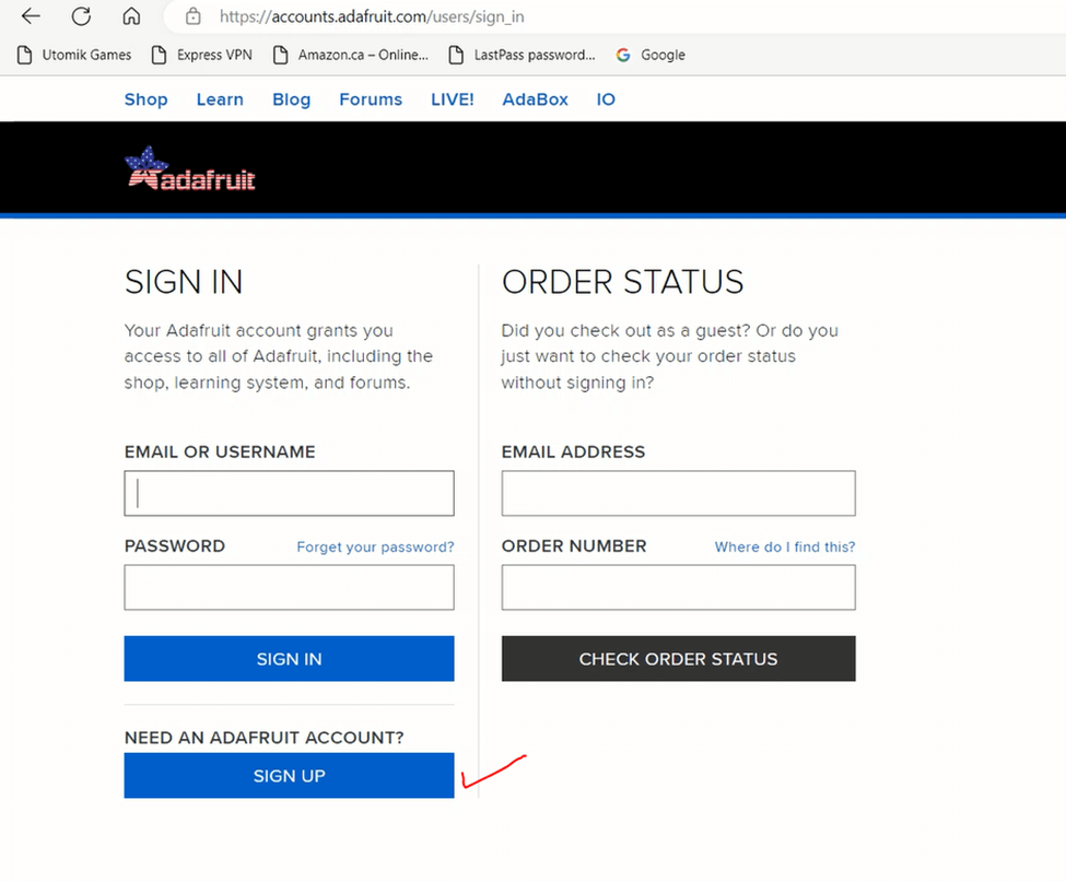
Go the Adafruit.io homepage
• Sign up for an account
• After sign-up, you can easily sign in using your email and password
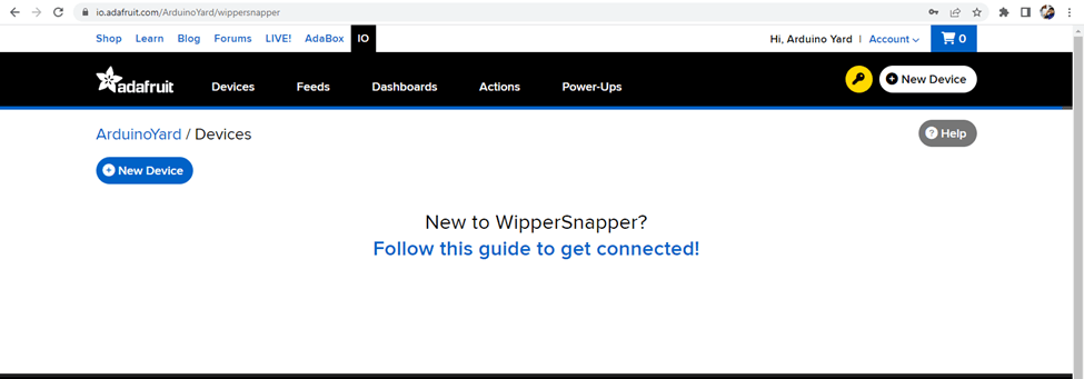
- After login successfully you will find the following screen
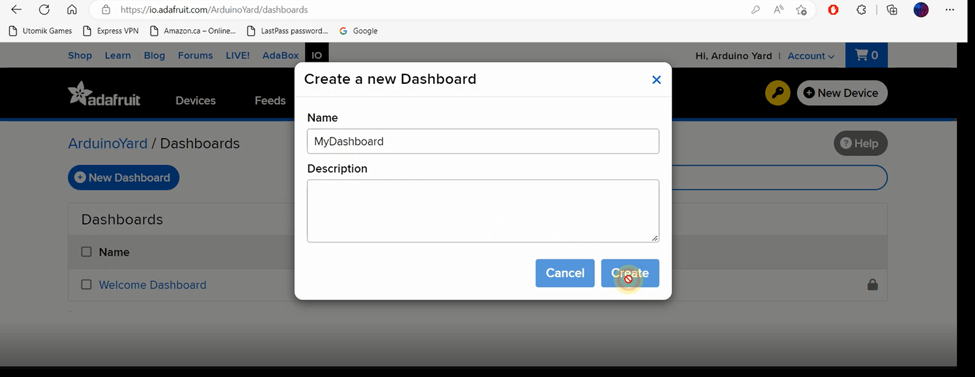
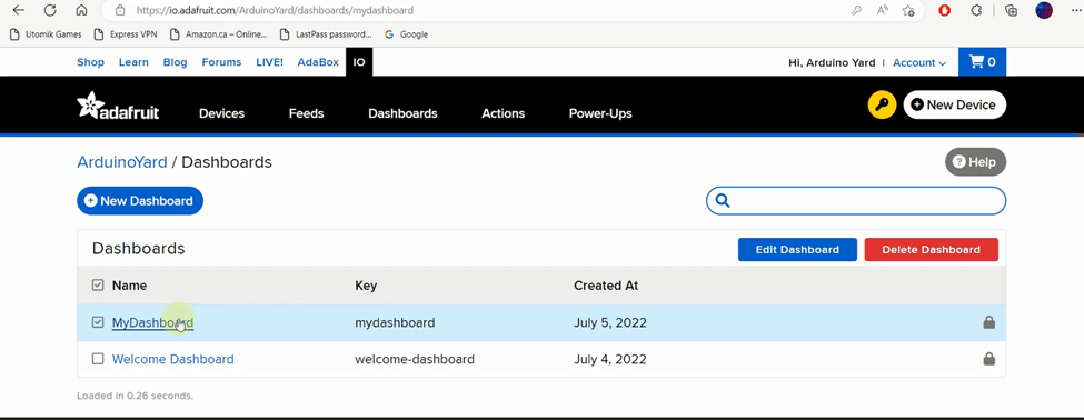
- Click on Dashboards, you will get following window, click on +New Dashboard
- After creating the new dashboard click on it from the dashboards list
- You will get a blank dashboard as below

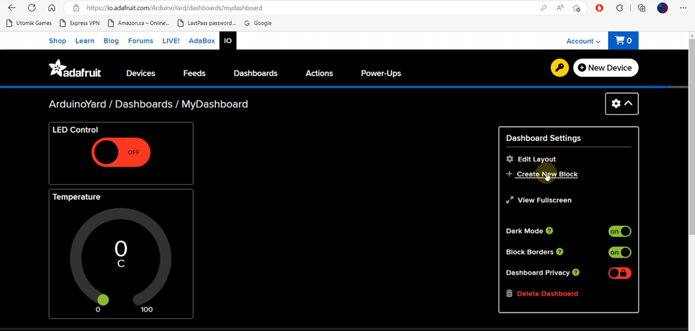
- Click on setting icon-> Create New Block
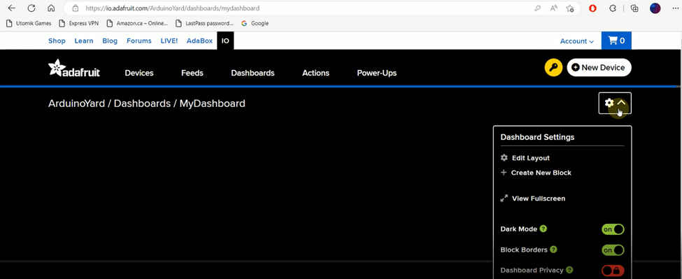
- You will get all the available blocks/gadgets as below. Click on Toggle gadget

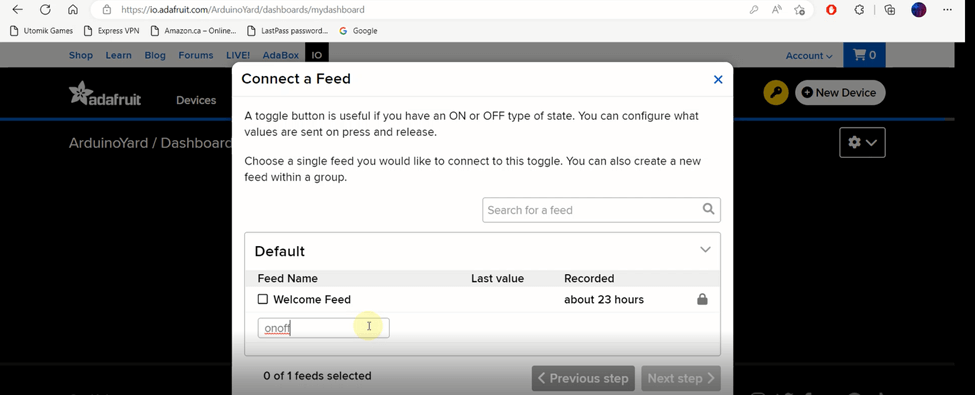
- Create a new feed give it a name onoff. This switch will toggle the LED connected on NodeMCU. Type the name of feed press ENTER
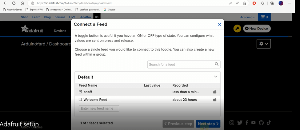
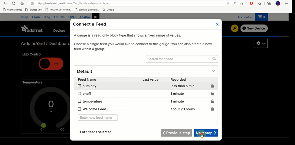
- Feed will be added in feeds list as below. Select the new created feed and press Next step
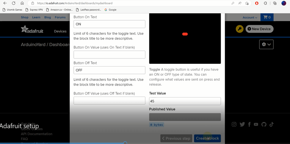
- Give this Toggle block a title LED Control
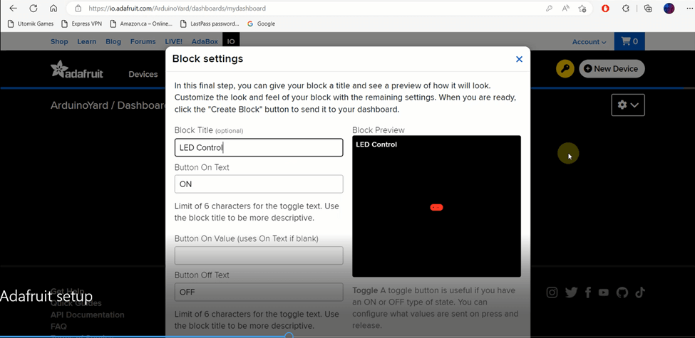
- Press Create Block
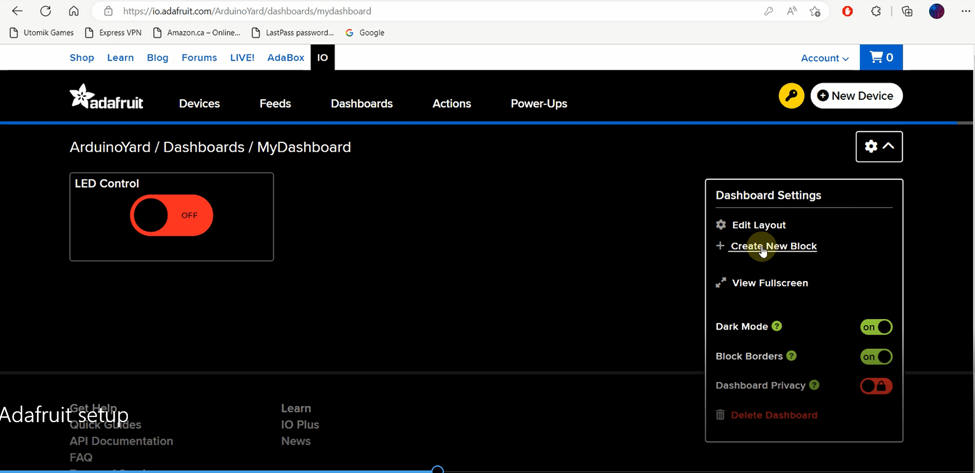
- We can see Toggle block is created to control the LED connected on NodeMCU. Now its time to create another block to show temperature readings on dashboard. Click on Setting icon->Create New Block.
- Create new feed name it as temperature. Now press ENTER
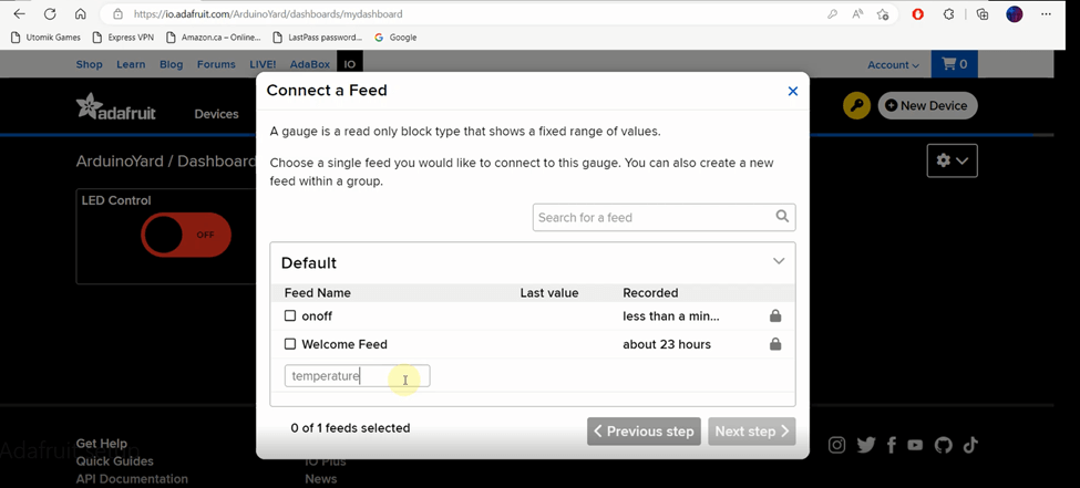
- We can see temperature feed is added in the feed list. Select the feed and press Next Step

- In this step, we will give name to block and set the unit. We can see how it is added for temperature. Focus on red ticks
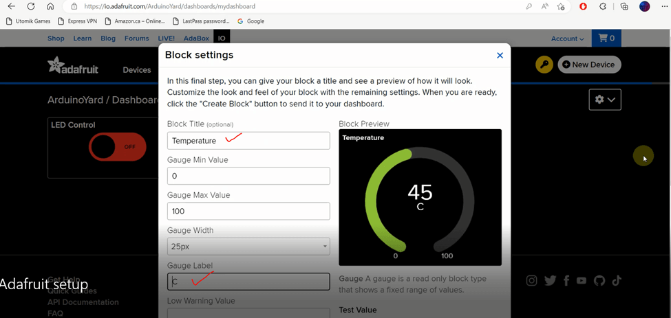
- After setting block name and unit, Click on Create Block as below

- We have created blocks for LED control and temperature readings. Now it’s time to create another block to show humidity readings on dashboard. Click on Setting icon->Create New Block.
- Create new feed, Name it is as humidity

- Click Enter and go to Next Step
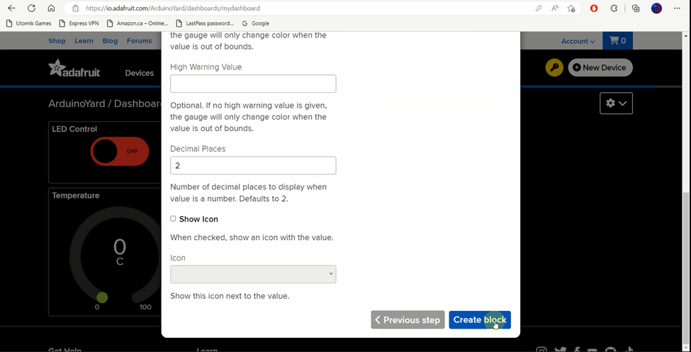
- Set the title of block as Humidity and its Unit % as shown below.

- Click on Create Block
- We can see our Dashboard is ready now
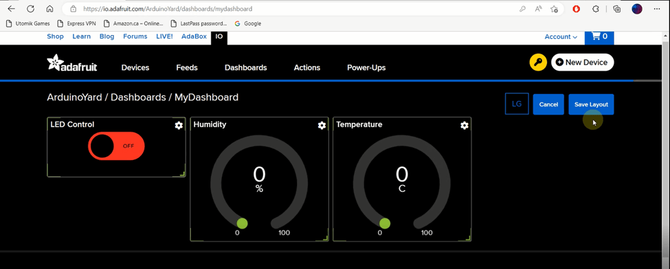
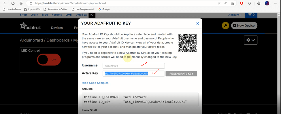
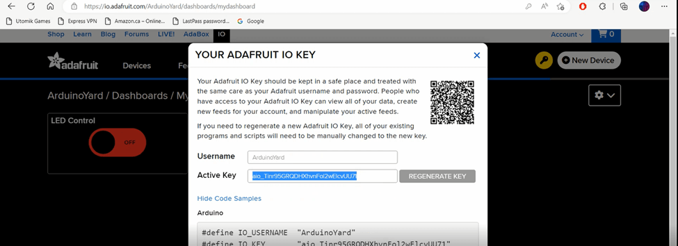
- Now click on Key icon as shown below

- Will guide you where to use these Username and Active Key later
Now that the dashboard setup is complete we can use DHT11 with Adafruit.io.
Arduino IDE Setup
To install the ESP8266 board in your Arduino IDE, follow these next instructions:
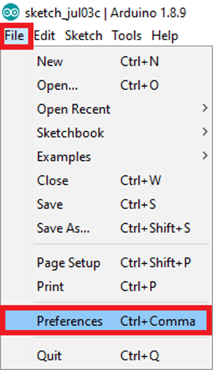
- In your Arduino IDE, go to File> Preferences
- Enter http://arduino.esp8266.com/stable/package_esp8266com_index.json into the “Additional Boards Manager URLs” field as shown in the figure below. Then, click the “OK” button:

Note: if you already have the ESP32 boards URL, you can separate the URLs with a comma as follows:
https://dl.espressif.com/dl/package_esp32_index.json, http://arduino.esp8266.com/stable/package_esp8266com_index.json
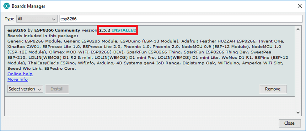
- Open the Boards Manager. Go to Tools > Board > Boards Manager

- Search for ESP8266 and press install button for the “ESP8266 by ESP8266 Community”
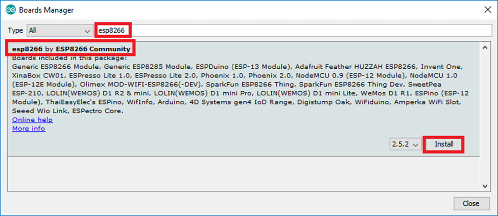
- That’s it. It should be installed after a few seconds.
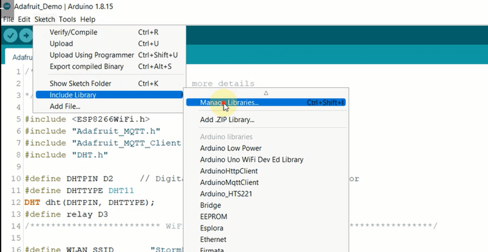
Adding Required Libraries
Go to Sketch -> Include Library-> Manage Libraries
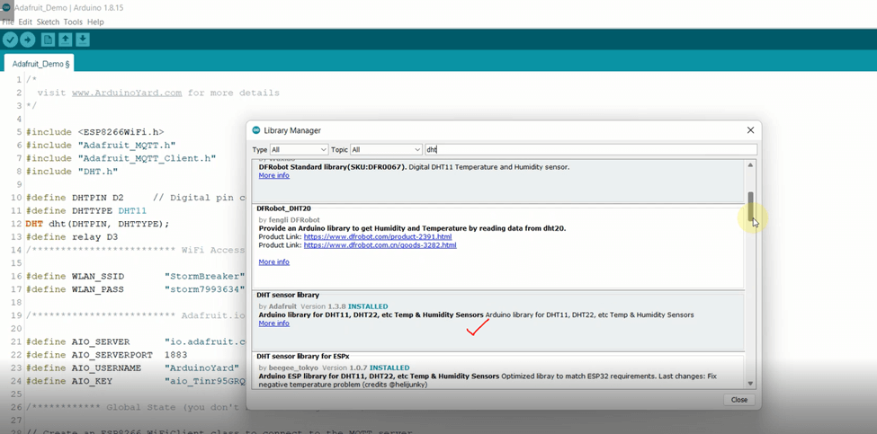
Search for Adafruit MQTT Library and install the as shown in the image below

Then search for DHT and install the shown DHT Sensor Library
Adding Required Keys
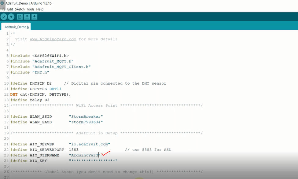
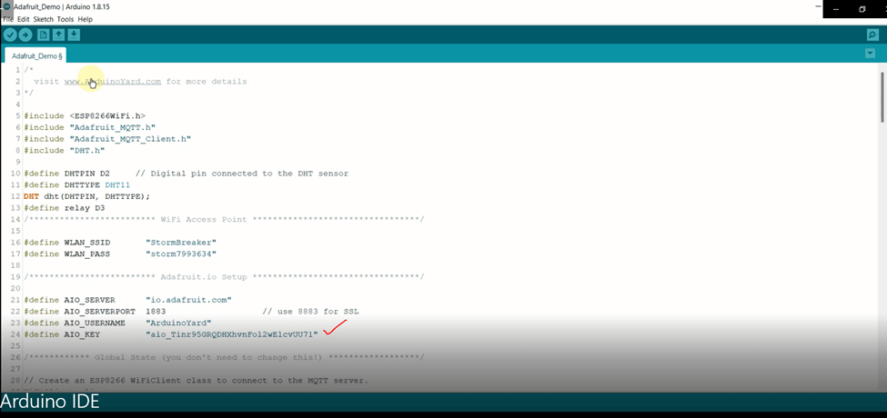
If you open the code, you need to add SSID and Password of your router to connect NodeMCU to internet. You need to update these 2 variables WLAN_SSID and WLAN_PASS.

When you are done with updating Wi-Fi credentials. You need to add Adafruit username and key. You can go to the dashboard click on Key icon which is along with New Device option as shown below. Copy the username and Active key and update variables AIO_USERNAME and AIO_KEY respectively.

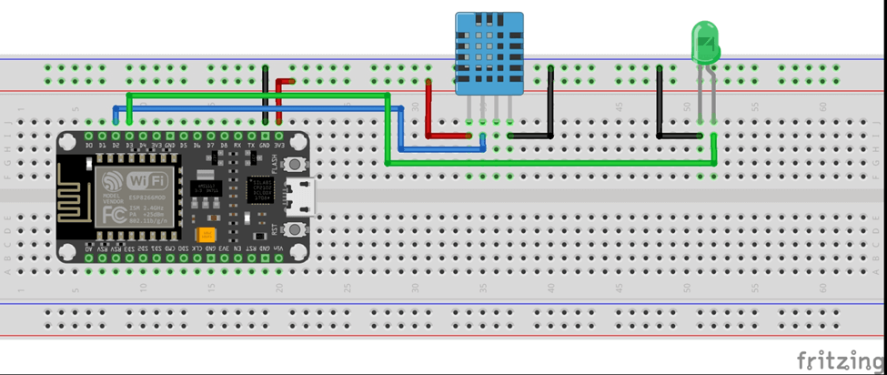
Wiring Diagram
We are done with all the necessary changes. Now its time to Wire up the circuit.
Code
Here is the complete code for this project:
/*
  visit www.ArduinoYard.com for more details
*/

#include <ESP8266WiFi.h>
#include "Adafruit_MQTT.h"
#include "Adafruit_MQTT_Client.h"
#include "DHT.h"

/************************* DHT Sensor Setup *********************************/

#define DHTPIN   D2     // Digital pin connected to the DHT sensor
#define DHTTYPE  DHT11  // Type of DHT Sensor, DHT11 or DHT22
DHT dht(DHTPIN, DHTTYPE);

#define ledPin   D3     // Connect LED on pin D3

/************************* WiFi Access Point *********************************/

#define WLAN_SSID       "************"   // Replace with your Wi-Fi SSID
#define WLAN_PASS       "************"   // Replace with your Wi-Fi Password

/************************* Adafruit.io Setup *********************************/

#define AIO_SERVER      "io.adafruit.com"
#define AIO_SERVERPORT  1883                                 // use 8883 for SSL
#define AIO_USERNAME    "***********"                        // Replace with your Adafruit IO Username
#define AIO_KEY         "********************************"   // Replace with your Adafruit IO Key

/************ Global State (you don't need to change this!) ******************/

// Create an ESP8266 WiFiClient class to connect to the MQTT server.
WiFiClient client;
// or... use WiFiClientSecure for SSL
//WiFiClientSecure client;

// Setup the MQTT client class by passing in the WiFi client and MQTT server and login details.
Adafruit_MQTT_Client mqtt(&client, AIO_SERVER, AIO_SERVERPORT, AIO_USERNAME, AIO_KEY);

/****************************** Feeds ***************************************/

// Setup feeds called 'temp' & 'hum' for publishing.
// Notice MQTT paths for AIO follow the form: <username>/feeds/<feedname>
// feedname should be the same as set in dashboard for temp and hum gauges
Adafruit_MQTT_Publish temp = Adafruit_MQTT_Publish(&mqtt, AIO_USERNAME "/feeds/temperature");  // feedname
Adafruit_MQTT_Publish hum = Adafruit_MQTT_Publish(&mqtt, AIO_USERNAME "/feeds/humidity");

// Setup a feed called 'onoff' for controlling LED.
Adafruit_MQTT_Subscribe onoffbutton = Adafruit_MQTT_Subscribe(&mqtt, AIO_USERNAME "/feeds/onoff");

void MQTT_connect();

int counter;

void setup() {
  Serial.begin(115200);
  delay(10);
  pinMode(ledPin, OUTPUT);
  Serial.println(F("Adafruit MQTT demo"));

  // Connect to WiFi access point.
  Serial.println(); Serial.println();
  Serial.print("Connecting to ");
  Serial.println(WLAN_SSID);

  WiFi.begin(WLAN_SSID, WLAN_PASS);
  while (WiFi.status() != WL_CONNECTED) {
    delay(500);
    Serial.print(".");
  }
  Serial.println();

  Serial.println("WiFi connected");
  Serial.println("IP address: "); Serial.println(WiFi.localIP());

  // Setup MQTT subscription for onoff feed.
  mqtt.subscribe(&onoffbutton);
  dht.begin();
}

void loop() {
  // Ensure the connection to the MQTT server is alive (this will make the first
  // connection and automatically reconnect when disconnected).  See the MQTT_connect
  // function definition further below.
  MQTT_connect();

  // this is our 'wait for incoming subscription packets' busy subloop
  // try to spend your time here


  Adafruit_MQTT_Subscribe *subscription;

  // Wait 2000 milliseconds, while we wait for data from subscription feed. After this wait, next code will be executed
  while ((subscription = mqtt.readSubscription(2000))) {
    if (subscription == &onoffbutton) {
      Serial.print(F("Got: "));
      Serial.println((char *)onoffbutton.lastread);

      char *value = (char *)onoffbutton.lastread;
      // Uncomment Serial print sections for debugging
      //Serial.print(F("Received: ")); // Display the value received from dashboard
      //Serial.println(value);

      // Apply message to OnOff
      String message = String(value);
      message.trim();
      if (message == "ON") {
        digitalWrite(ledPin, HIGH);
        //Serial.println("LED ON");
      }
      if (message == "OFF") {
        digitalWrite(ledPin, LOW);
        //Serial.println("LED OFF");
      }
    }
  }

  // DHT11 Sensor readings may also be up to 2 seconds 'old' (its a very slow sensor)
  float h = dht.readHumidity();
  // Read temperature as Celsius (the default)
  float t = dht.readTemperature();

  Serial.print(F("Humidity: "));
  Serial.print(h);
  Serial.print(F("%  Temperature: "));
  Serial.print(t);
  Serial.print(F("°C "));

  // Now we can publish stuff!
  Serial.print(F("\nSending Humidity val "));

  if (! hum.publish(h)) {
    Serial.println(F("Failed"));
  } else {
    Serial.println(F("OK!"));
  }
  Serial.print(F("\nSending Temperature val "));
  if (! temp.publish(t)) {
    Serial.println(F("Failed"));
  } else {
    Serial.println(F("OK!"));
  }

  // ping the server to keep the mqtt connection alive
  // NOT required if you are publishing once every KEEPALIVE seconds
  /*
    if(! mqtt.ping()) {
    mqtt.disconnect();
    }
  */

}

// Function to connect and reconnect as necessary to the MQTT server.
// Should be called in the loop function and it will take care if connecting.
void MQTT_connect() {
  int8_t ret;

  // Stop if already connected.
  if (mqtt.connected()) {
    return;
  }

  Serial.print("Connecting to MQTT... ");

  uint8_t retries = 3;
  while ((ret = mqtt.connect()) != 0) { // connect will return 0 for connected
    Serial.println(mqtt.connectErrorString(ret));
    Serial.println("Retrying MQTT connection in 5 seconds...");
    mqtt.disconnect();
    delay(5000);  // wait 5 seconds
    retries--;
    if (retries == 0) {
      // basically die and wait for WDT to reset me
      while (1);
    }
  }
  Serial.println("MQTT Connected!");
}
Final Results using DHT11 with Adafruit.IO
Compile the code and upload the code to NodeMCU and you will get the results like this:

You will be able to see the DHT11 temperature and humidity readings on the Adafruit dashboard. You will also be able to control the LED using the LED Control switch on the dashboard.
Conclusion
In summary, this Arduino project uses DHT11 with Adafruit.io and highlights it’s power in IoT. Controlling an LED remotely showcases global appliance management. Displaying Temperature/Humidity on Adafruit’s gadgets reveals its versatility without complex dashboards.
The process is simple: drag, drop, and connect microcontrollers like ESP32/ESP8266 with Adafruit by providing basic details. No need for intricate setups. This simplicity unleashes a range of possibilities.
From home automation to smart greenhouses, Adafruit.io offers a seamless solution. Just input feed names, usernames, and Active keys. Thanks for reading; we hope this insight proves valuable for your future projects.
Detailed YouTube Video
You may also like:
DIY HOME SECURITY: ARDUINO INTRUDER ALARM SYSTEM WITH ESP32 & BLYNK CLOUD INTEGRATION