
Table of Contents
Overview
Welcome to this comprehensive tutorial on building your very own Arduino Intruder Alarm System. In this tutorial, we’ll guide you through the process of creating a robust and effective security system using the Beetle ESP32 C3 board, DF robot mm wave Radar (human presence sensor), and Blynk Cloud integration. This project will enable you to monitor and control your security system remotely, receive real-time alerts, and ensure maximum security for your home or workspace.
Components
- Beetle ESP32 C3 board: This compact and powerful development board serves as the brain of our Arduino Intruder Alarm System. It provides Wi-Fi connectivity, GPIO pins for interfacing with other components, and easy programming capabilities.
- DF robot mm wave Radar: The mm wave Radar sensor accurately detects human presence within its detection range. It ensures reliable detection while minimizing false alarms, making it an ideal choice for our project.
- Buzzer: The buzzer is used as an audible alarm to alert you when an intruder is detected. It provides an additional layer of security by attracting attention and signaling potential threats.
- LED (Built-in): The built-in LED on the Beetle ESP32 C3 board serves as a visual indicator, providing feedback on the system’s status and the presence of an intruder.
- Wi-Fi Router: A Wi-Fi router is required to establish a connection between the Arduino board and the Blynk Cloud, enabling remote access and control of the Arduino Intruder Alarm System.
Blynk Dashboard Setup (Web)
To effectively monitor and control your Arduino Intruder Alarm System, you can set up the Blynk dashboard using the Blynk Cloud web interface. Blynk provides an intuitive and user-friendly platform for managing your IoT projects. Follow the steps below to set up the Blynk dashboard for your project using the web interface:
- Visit Blynk Cloud:
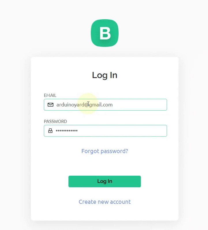
- Open your web browser and go to the Blynk Cloud website (https://blynk.cloud/).
- If you don’t have an account, click on “Create New Account” to sign up. If you already have an account, log in using your credentials.
- Create a New Project:
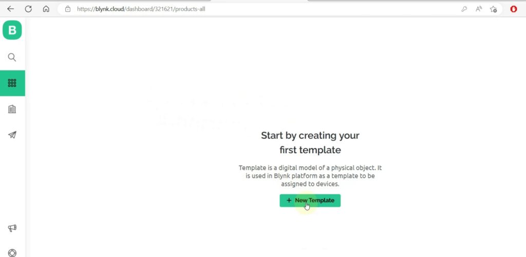
- Once you are logged in, go to the Templates tab and click on the + New Template button.
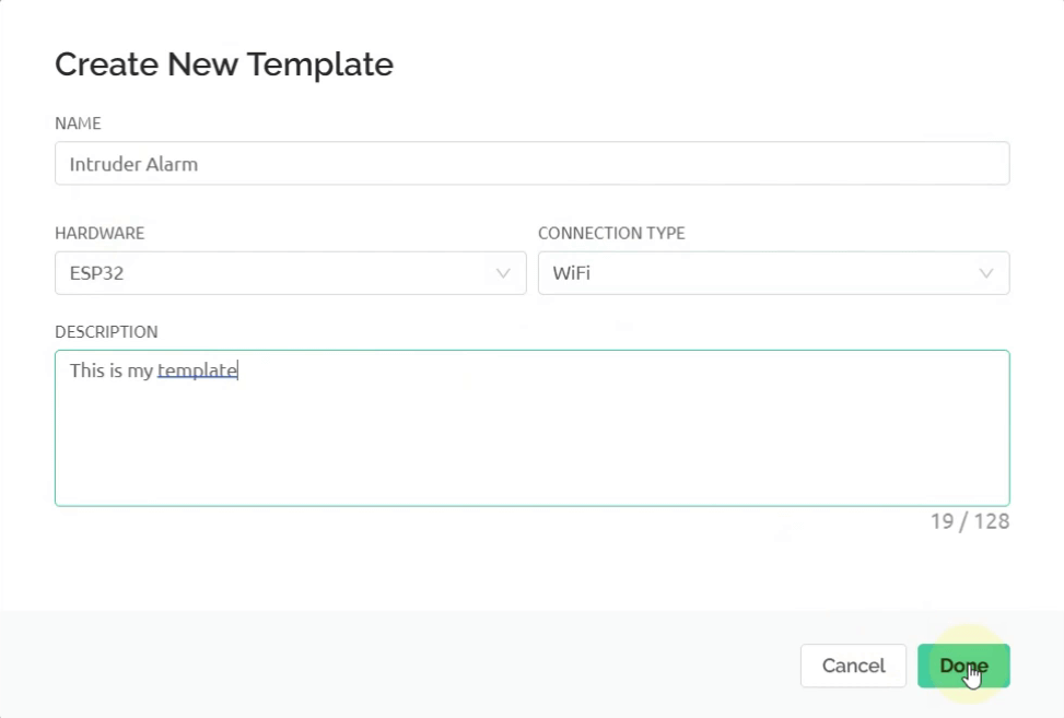
- Enter a name for your template, such as “Intruder Alarm“. Select the hardware as ESP32 and connection type as WiFi. Click Done.
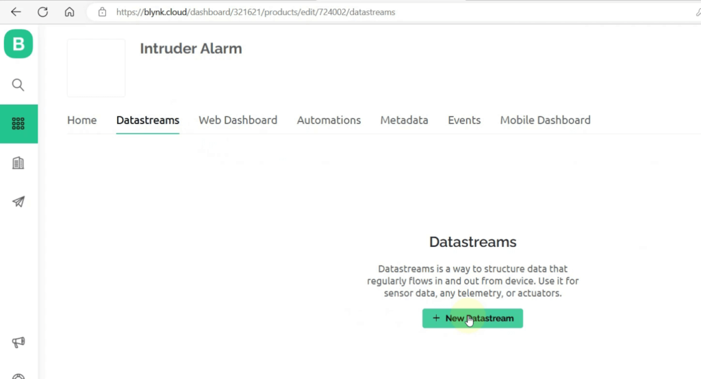
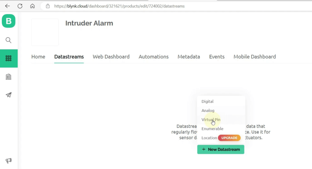
- Go to Datastreams tab. Click on + New Datastream
- Click Virtual Pin to get the value of sensor
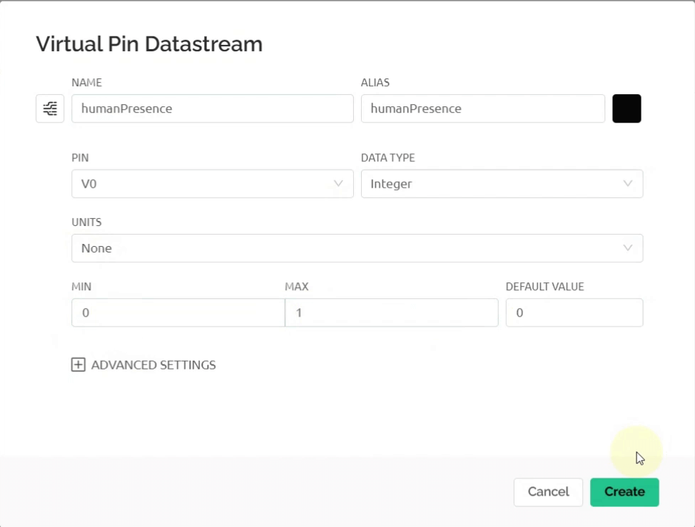
- Use the following settings and click Create
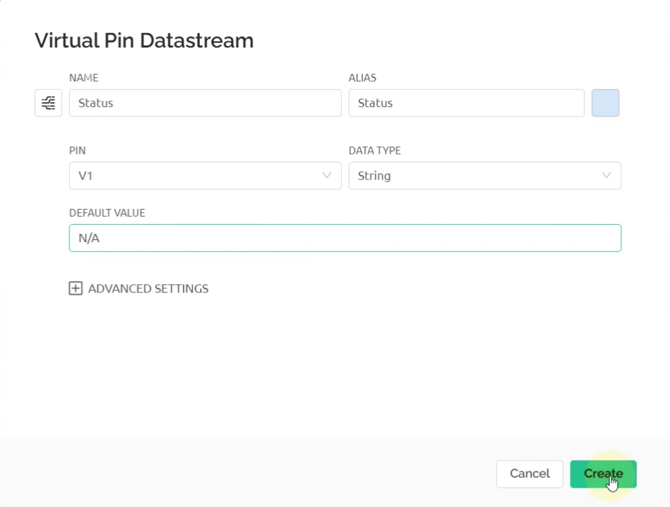
- Add another Virtual Pin for device status, use the following settings and click Create
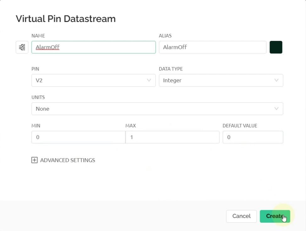
- Add another virtual pin for Alarm OFF button, use the following settings and click Create
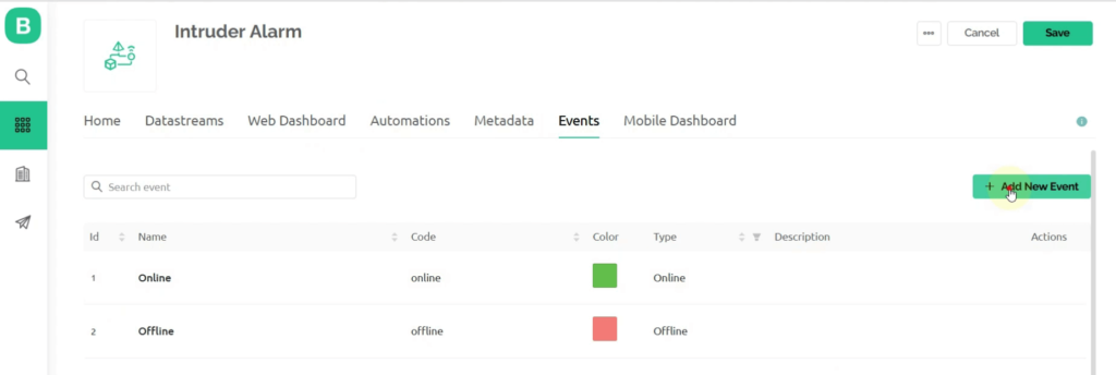
- Go to the Events tab. Click on + Add New Event to create an intruder alert notification
- Use the following settings. Add the description you want to display on the notification.
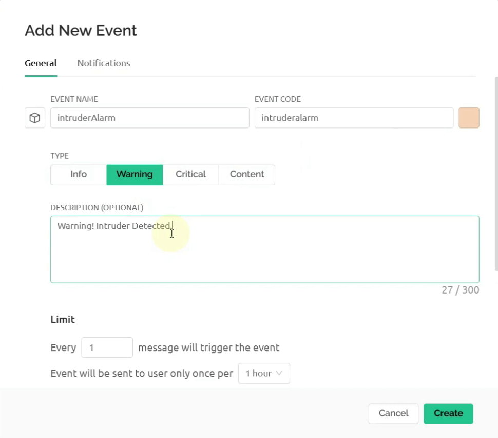
- Set the limits as shown and turn ON the Show event in Notifications and Send event to Timeline buttons

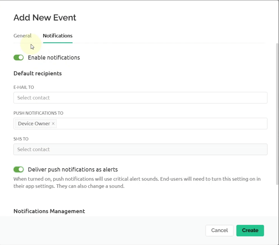
- Go to the Notifications tab. Turn ON Enable Notifications. Push notifications to the Device Owner and turn ON the Deliver push Notifications button. Click Create
- Go to the Web Dashboard tab. Drag the LED, Label and Switch widgets to the dashboard.
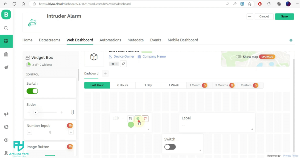
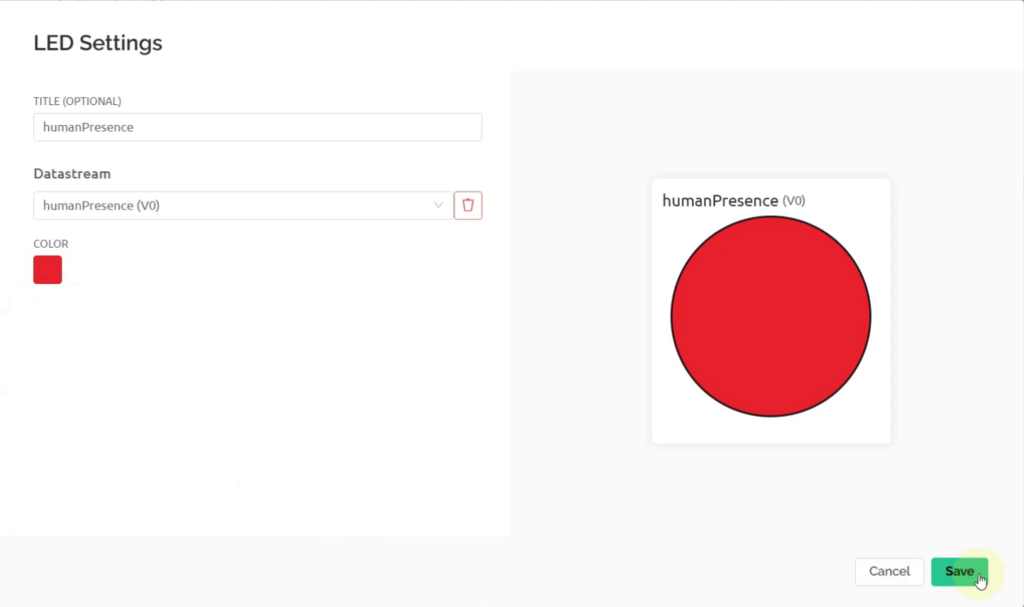
- Open the LED settings and set them as follows. Click Save
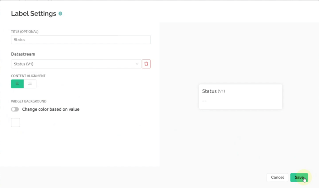
- Open the Label settings and set them as follows. Click Save
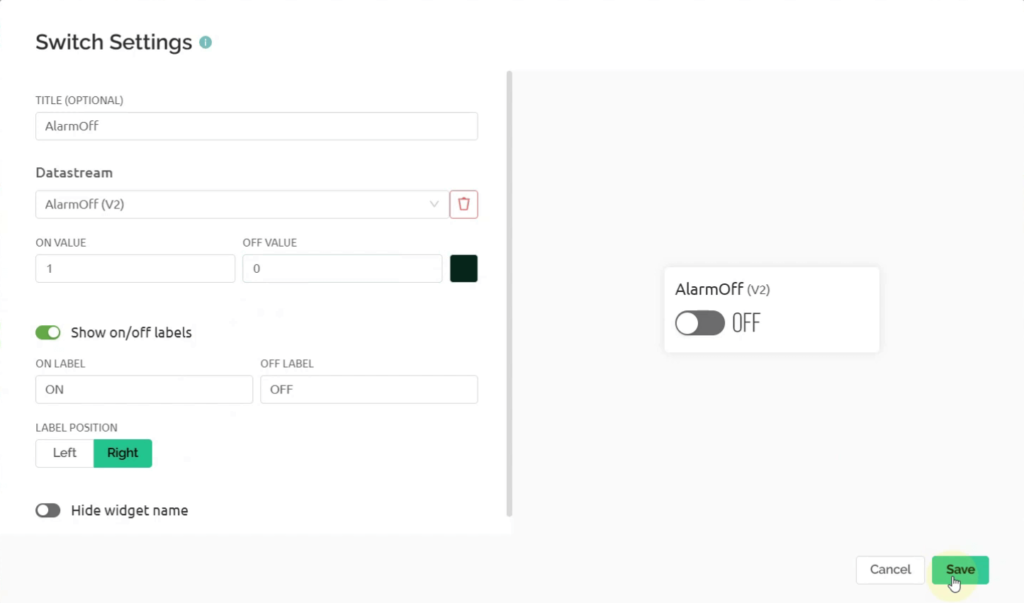
- Open the Switch settings and set them as follows. Click Save
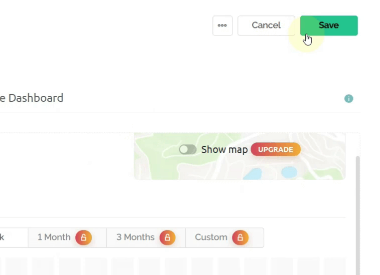
- Click Save on the top right to save the dashboard.
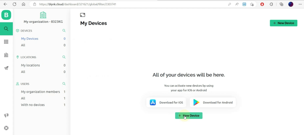
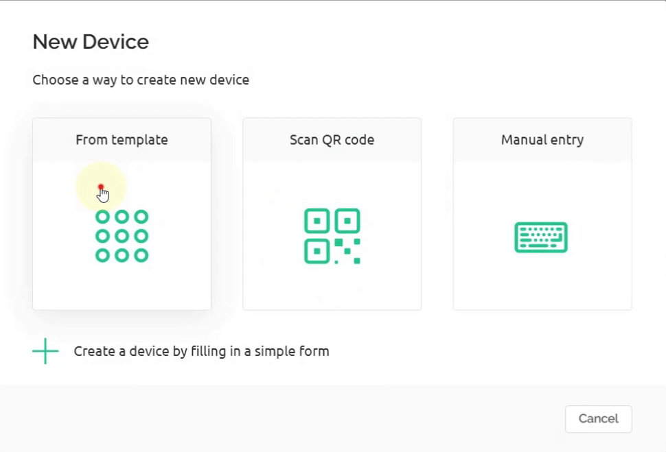
- Now go to the Devices tab. Click on + New Device to add your device.
- Select From Template
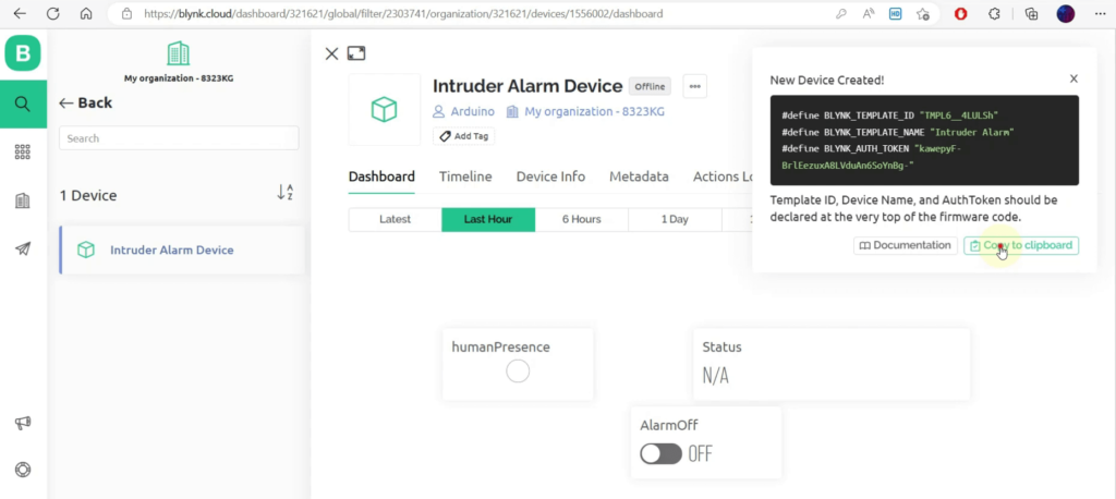
- Name the device as Intruder Alarm Device. Click Create

- On the top right you can see your device’s Template ID, Name and Auth Token. Copy these 3 lines, we will need these later in the code.
Blynk App Setup
- Install the Blynk IoT app in your phone and login using your credentials.
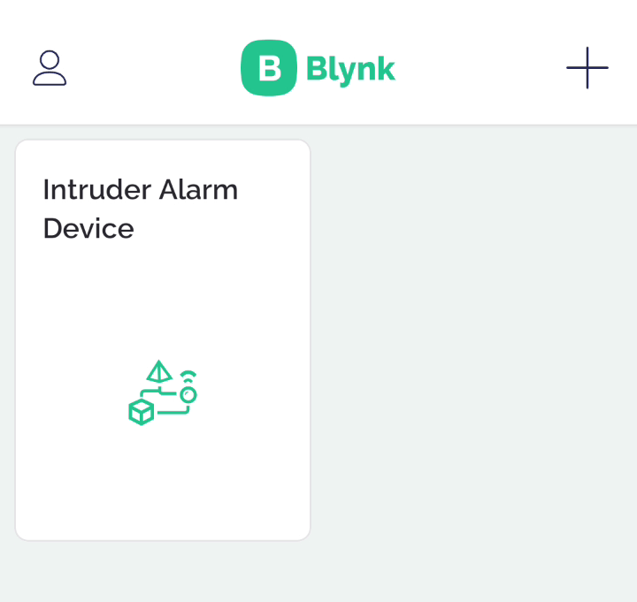
- You will see a device named “Intruder Alarm Device already created. Open this card
- Once opened, click on the Ratchet symbol on the bottom right.
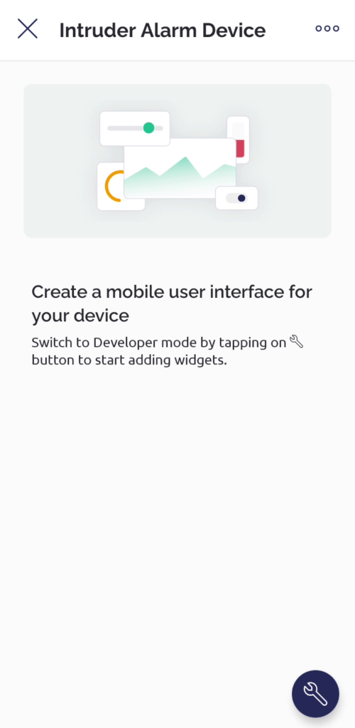
- Click on the + button on the top right. Add the LED, Label and Button widgets onto the dashboard. Configure the settings as done previously in the web dashboard.

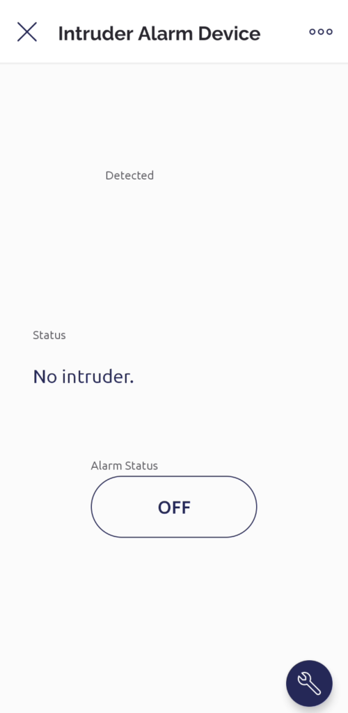
- Now go back. The dashboard should look something like this:
Wiring Diagram
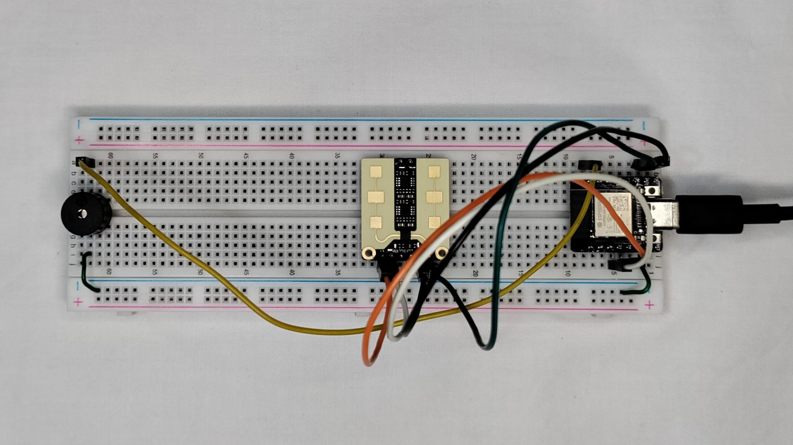
Wire your circuit as shown below:

Installing the Libraries
Before you can start building the Arduino Intruder Alarm System, you’ll need to install the required libraries. These libraries provide the necessary functions and features for seamless integration of the components and communication with Blynk Cloud. Follow the steps below to install the libraries:
- Blynk Library:
With the Library Manager still open, search for “Blynk”.
Find “Blynk” by Volodymyr Shymanskyy and click on “Install”.
Allow the installation process to finish.
- DFRobot_mmWave_Radar Library:
Download the DFRobot_mmWave_Radar library from the GitHub repository (https://github.com/DFRobot/DFRobot_mmWave_Radar).
Extract the downloaded zip file.
Open the Arduino IDE.
Go to “Sketch” -> “Include Library” -> “Add .ZIP Library”.
Browse and select the extracted DFRobot_mmWave_Radar library folder.
Click on “Open” to install the library.
Once you have installed all the required libraries, you are ready to proceed with uploading the code for the Arduino Intruder Alarm System.
Code
Here is the complete code for this project:
/*
  Code for Arduino Intruder Alarm System using ESP32
  Created by ArduinoYard.com
*/
/* Comment this out to disable prints and save space */
#define BLYNK_PRINT Serial

/* Fill in information from Blynk Device Info here */
#define BLYNK_TEMPLATE_ID "TMPL6__4LULSh"
#define BLYNK_TEMPLATE_NAME "Intruder Alarm"
#define BLYNK_AUTH_TOKEN "kawepyF-BrlEezuxA8LVduAn6SoYnBg-"

#include <WiFi.h>
#include <WiFiClient.h>
#include <BlynkSimpleEsp32.h>
#include <DFRobot_mmWave_Radar.h>

// Your WiFi credentials.
// Set password to "" for open networks.
char ssid[] = "mySSID";
char pass[] = "myPass";

HardwareSerial mySerial(1);  // Using Hardware Serial 1 of the ESP32

DFRobot_mmWave_Radar sensor(&mySerial);  // DFrobot mmwave sensor object

#define alarmPin  7

int val = 0;
unsigned long lastMillis = 0;
unsigned long lastEventMillis = 0;
unsigned long updateInterval = 1000;   // Interval for updating values on Blynk cloud, min = 1 sec
unsigned long eventInterval = 60000;   // Interval for logging event/sending notification, 1 minute

BLYNK_WRITE(V2) {
  int alarmVal = param.asInt(); // assigning incoming value from pin V1 to a variable

  if (alarmVal == 0) {  // If Alarm OFF button pressed on app/web dashboard
    digitalWrite(alarmPin, LOW);  // Turn OFF alarm
    Serial.println("Alarm OFF."); // Print on Serial Monitor
  }
  else {
    digitalWrite(alarmPin, HIGH);  // Turn ON alarm
    Serial.println("Alarm ON."); // Print on Serial Monitor
  }
}

void setup() {
  Serial.begin(115200);  // Open Serial Monitor at 115200 Baud rate
  mySerial.begin(115200, SERIAL_8N1, 20, 21);  // RX, TX
  pinMode(LED_BUILTIN, OUTPUT);  // Set the built-in LED as Output
  pinMode(alarmPin, OUTPUT);     // Set Alarm pin as output
  digitalWrite(alarmPin, LOW);   // Turn OFF alarm at start

  sensor.factoryReset();     // Restore to the factory settings
  sensor.DetRangeCfg(0, 1);  // The detection range is as far as 9m
  sensor.OutputLatency(0, 0);

  Blynk.begin(BLYNK_AUTH_TOKEN, ssid, pass);  // Connect to Wi-Fi and Blynk
}

void loop() {

  if (millis() - lastMillis >= updateInterval) {  // If 1 second has passed, update the values on Blynk cloud
    lastMillis = millis();        // Save the update time

    Blynk.virtualWrite(V0, val);  // Push value on V0

    if (val == 1) {  // If intruder detected
      Blynk.virtualWrite(V1, "Warning! Intruder detected."); // Send a warning status string on V1
      digitalWrite(alarmPin, HIGH);                          // Turn ON alarm if intruder detected
      Blynk.virtualWrite(V2, 1);                             // Push the alarm status on V2
      if (millis() - lastEventMillis >= eventInterval) {     // If 1 minute has passed since the last intruder notification
        lastEventMillis = millis();
        Blynk.logEvent("intruderalarm");  // Loga new event and send notification
      }
    }
    else {                                     // If no intruder detected
      Blynk.virtualWrite(V1, "No intruder.");  // Set the status as normal
    }

    Blynk.run();  // Update the values on Blynk
  }

  val = sensor.readPresenceDetection();  // Continuously detect the human presence
  digitalWrite(LED_BUILTIN, val);        // Turn ON/OFF the built-in LED according to the val
  Serial.println(val);                   // Print the val on Serial monitor
}

// Arduino Intruder Alarm System using ESP32 - END
Things to change in the code:
- Replace Line#6-7-8 with the 3 lines you copied from Blynk Dashboard.
- On Line#17-18 replace the ssid and pass according to your WiFi SSID and Password.
Final Results
Here is how the hardware will look for the Arduino Intruder Alarm System:
Once the code is uploaded, open the Serial Monitor at 115200 baud rate to observe the readings.
Once device is connected to WiFi and Blynk, you should be able to see the readings. 0 will be printed if no one is detected. 1 will be printed when human presence is detected.

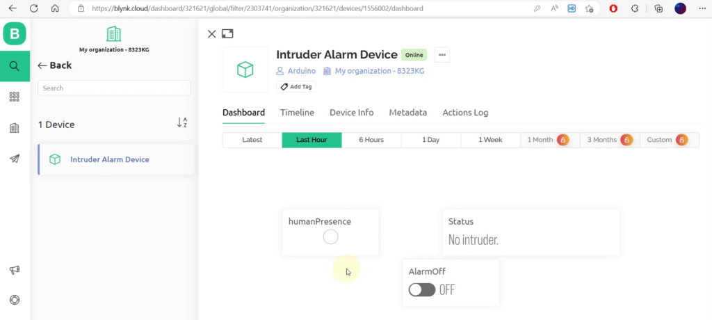
Now open the Blynk web dashboard to monitor the system. When no intruder is detected, the LED will be OFF, Status will say “No Intruder.” and the Alarm is OFF.
When an intruder is detected, the LED will be ON/RED, Status will say “Warning! Intruder detected.” and the Alarm is ON. The Alarm will not turn OFF until the user turns OFF it manually from the Web or Mobile app dashboard using the Alarmoff button.

When an intruder is detected, the mobile device will immediately get a warning notification as shown below:
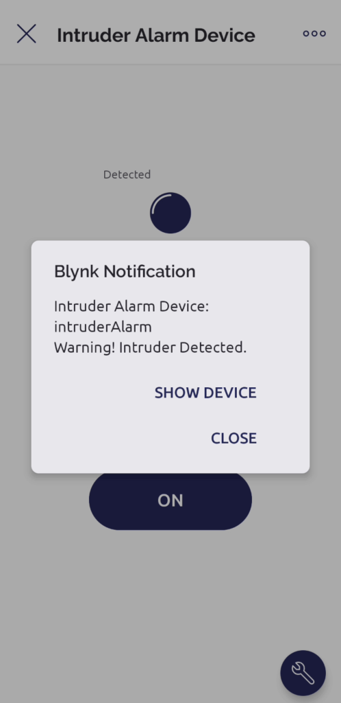
User can also go to the notifications section to see the past alerts information.

Conclusion
Congratulations on successfully completing the Arduino Intruder Alarm System project! By following this comprehensive tutorial, you have successfully built a robust security system using the Beetle ESP32 C3 board, DF robot mm wave Radar, and Blynk Cloud integration. Throughout this journey, you have gained valuable knowledge in hardware setup, sensor integration, Blynk Cloud configuration, and Arduino programming.
By implementing the code snippets and customizing the Blynk dashboard, you have created a reliable and user-friendly Arduino Intruder Alarm System. The mm wave Radar sensor accurately detects human presence, allowing the alarm to be activated whenever an intruder is detected. Through the seamless integration with Blynk Cloud, you can remotely monitor and control the security system using the Blynk app, providing you with real-time status updates and the ability to deactivate the alarm at your convenience.
With the Arduino Intruder Alarm System’s completion, you are now equipped with the skills and understanding to explore further possibilities in the fascinating world of Arduino and IoT projects. Share your achievements with the community, engage in discussions, and inspire others to embark on their own security system projects.
We extend our gratitude for joining us on this rewarding journey to create a reliable and intelligent Arduino Intruder Alarm System. Stay tuned for more exciting projects and tutorials as you continue to explore the vast potential of Arduino and IoT technologies.
Remember, the skills and knowledge you have acquired can be applied to various other projects, empowering you to create innovative solutions that enhance security, automation, and connectivity in your surroundings.
Thank you for your dedication and enthusiasm. Happy tinkering!
Detailed YouTube Video
Here is the detailed YouTube video for this project:
You may also like:
DHT11 WITH ADAFRUIT.IO: TEMP AND HUM MONITORING WITH NODEMCU
If i set up a camera what will i do. Please give me a suggestion.
To setup a camera and do live video monitoring you can use an ESP32 Cam.