Table of Contents
Overview
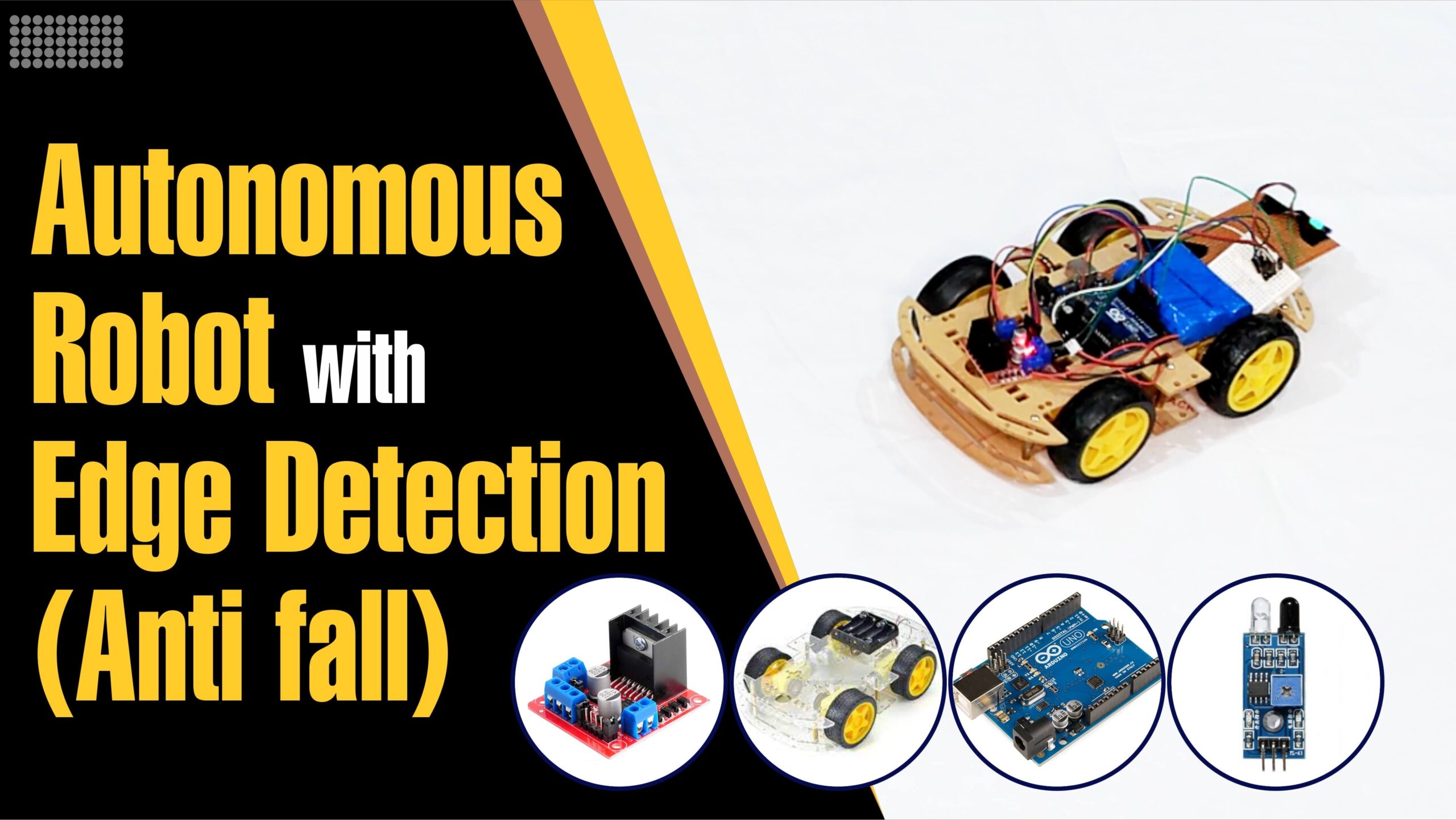
In this tutorial, we will guide you through the process of constructing an autonomous edge-detection robot using Arduino. By integrating an infrared (IR) sensor and precise motor control, we will enable the robot to independently navigate its surroundings, detect edges, and avoid potential falls. Whether you’re a beginner or an experienced Arduino enthusiast, this project will enhance your understanding of robotics and DIY electronics. Join us as we delve into the exciting world of technology and bring our robot to life!
Watch now on YouTube.
Components Required
- Arduino UNO: The brain of our autonomous edge-detection robot.
- L298N Motor Driver: To control the four motors.
- Car Chassis: Provides a sturdy base for the robot.
- Infrared (IR) Sensor: Detects edges and potential obstacles.
- 12V Battery: Powers the motors and Arduino.
Wiring Diagram
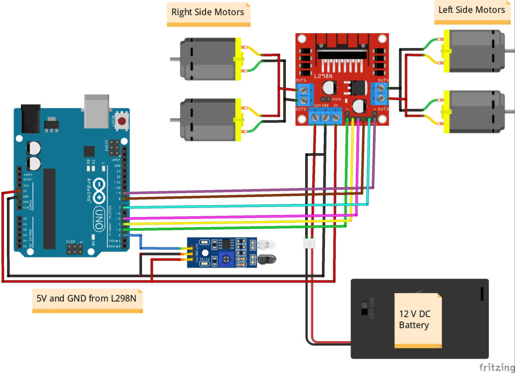
To build our autonomous edge-detection robot, we need to connect the components correctly as shown in the following diagram. Ensure a secure and reliable connection between the Arduino, motor driver, IR sensor, and power source.
Code for Edge-Detection Robot
/*
  Autonomous Edge-Detection Robot with Arduino
  Created by ArduinoYard.com
*/
// Define the pins for the IR sensor
const int IR_SENSOR_PIN = 2;

// Define the pins for the L298N motor driver
const int MOTOR_A_ENABLE_PIN = 3;
const int MOTOR_A_IN1_PIN = 4;
const int MOTOR_A_IN2_PIN = 5;
const int MOTOR_B_ENABLE_PIN = 9;
const int MOTOR_B_IN1_PIN = 8;
const int MOTOR_B_IN2_PIN = 7;

// Define the speed for the motors, change as required. Too fast and robot can fall off.
const int MOTOR_SPEED = 100;

void setup() {
  // Set the IR sensor pin as an input
  pinMode(IR_SENSOR_PIN, INPUT);

  // Set the motor driver pins as outputs
  pinMode(MOTOR_A_ENABLE_PIN, OUTPUT);
  pinMode(MOTOR_A_IN1_PIN, OUTPUT);
  pinMode(MOTOR_A_IN2_PIN, OUTPUT);
  pinMode(MOTOR_B_ENABLE_PIN, OUTPUT);
  pinMode(MOTOR_B_IN1_PIN, OUTPUT);
  pinMode(MOTOR_B_IN2_PIN, OUTPUT);

  // Set the motor enable pins to high to enable the motors
  digitalWrite(MOTOR_A_ENABLE_PIN, HIGH);
  digitalWrite(MOTOR_B_ENABLE_PIN, HIGH);
}

// Function to move the car forward
void moveForward() {
  digitalWrite(MOTOR_A_IN1_PIN, HIGH);
  digitalWrite(MOTOR_A_IN2_PIN, LOW);
  digitalWrite(MOTOR_B_IN1_PIN, HIGH);
  digitalWrite(MOTOR_B_IN2_PIN, LOW);
  analogWrite(MOTOR_A_ENABLE_PIN, MOTOR_SPEED);
  analogWrite(MOTOR_B_ENABLE_PIN, MOTOR_SPEED);
}

// Function to move the car backward
void moveBackward() {
  digitalWrite(MOTOR_A_IN1_PIN, LOW);
  digitalWrite(MOTOR_A_IN2_PIN, HIGH);
  digitalWrite(MOTOR_B_IN1_PIN, LOW);
  digitalWrite(MOTOR_B_IN2_PIN, HIGH);
  analogWrite(MOTOR_A_ENABLE_PIN, MOTOR_SPEED);
  analogWrite(MOTOR_B_ENABLE_PIN, MOTOR_SPEED);
}

// Function to stop the car
void stopCar() {
  digitalWrite(MOTOR_A_IN1_PIN, LOW);
  digitalWrite(MOTOR_A_IN2_PIN, LOW);
  digitalWrite(MOTOR_B_IN1_PIN, LOW);
  digitalWrite(MOTOR_B_IN2_PIN, LOW);
  analogWrite(MOTOR_A_ENABLE_PIN, 0);
  analogWrite(MOTOR_B_ENABLE_PIN, 0);
}

// Function to turn the car right
void turnRight() {
  digitalWrite(MOTOR_A_IN1_PIN, LOW);
  digitalWrite(MOTOR_A_IN2_PIN, HIGH);
  digitalWrite(MOTOR_B_IN1_PIN, HIGH);
  digitalWrite(MOTOR_B_IN2_PIN, LOW);
  analogWrite(MOTOR_A_ENABLE_PIN, MOTOR_SPEED);
  analogWrite(MOTOR_B_ENABLE_PIN, MOTOR_SPEED);
}

// Function to turn the car left
void turnLeft() {
  digitalWrite(MOTOR_A_IN1_PIN, HIGH);
  digitalWrite(MOTOR_A_IN2_PIN, LOW);
  digitalWrite(MOTOR_B_IN1_PIN, LOW);
  digitalWrite(MOTOR_B_IN2_PIN, HIGH);
  analogWrite(MOTOR_A_ENABLE_PIN, MOTOR_SPEED);
  analogWrite(MOTOR_B_ENABLE_PIN, MOTOR_SPEED);
}

void loop() {
  // Read the value from the IR sensor
  int irSensorValue = digitalRead(IR_SENSOR_PIN);

  // If the IR sensor detects an edge, stop the car and turn right
  if (irSensorValue == HIGH) {
    stopCar();
    delay(1000);
    moveBackward();
    delay(500);
    turnRight();
    delay(1500);
    // Adjust the delays according to your requirement, speed and surface.
    // Your robot might need to move/stop more or less depending on these factors.
  }
  // If no edge is detected, move the car forward
  else {
    moveForward();
  }
}
// Autonomous Edge-Detection Robot with Arduino - END
Understanding the Code
Let’s take a closer look at the code that powers our autonomous edge-detection robot. By understanding how the code functions, you can gain insight into how the robot operates and make any necessary modifications.
// Define the pins for the IR sensor
const int IR_SENSOR_PIN = 2;
At the beginning of the code, we define the pin number (2 in this case) for the IR sensor. This pin will be used to connect the IR sensor to the Arduino board.
// Define the pins for the L298N motor driver
const int MOTOR_A_ENABLE_PIN = 3;
const int MOTOR_A_IN1_PIN = 4;
const int MOTOR_A_IN2_PIN = 5;
const int MOTOR_B_ENABLE_PIN = 9;
const int MOTOR_B_IN1_PIN = 8;
const int MOTOR_B_IN2_PIN = 7;
Next, we define the pin numbers for the L298N motor driver. These pins will be connected to the respective control pins on the motor driver, enabling us to control the robot’s motors.
// Define the speed for the motors, change as required. Too fast and robot can fall off.
const int MOTOR_SPEED = 100;
Here, we set the speed at which the motors will operate. It is important to find the right balance; if the speed is too high, the robot may lose control and fall off edges.
void setup() {
  // Set the IR sensor pin as an input
  pinMode(IR_SENSOR_PIN, INPUT);

  // Set the motor driver pins as outputs
  pinMode(MOTOR_A_ENABLE_PIN, OUTPUT);
  pinMode(MOTOR_A_IN1_PIN, OUTPUT);
  pinMode(MOTOR_A_IN2_PIN, OUTPUT);
  pinMode(MOTOR_B_ENABLE_PIN, OUTPUT);
  pinMode(MOTOR_B_IN1_PIN, OUTPUT);
  pinMode(MOTOR_B_IN2_PIN, OUTPUT);

  // Set the motor enable pins to high to enable the motors
  digitalWrite(MOTOR_A_ENABLE_PIN, HIGH);
  digitalWrite(MOTOR_B_ENABLE_PIN, HIGH);
}
In the setup() function, we configure the pins for the IR sensor and motor driver. The IR sensor pin is set as an input, while the motor driver pins are set as outputs. Additionally, we set the motor enable pins to HIGH to enable the motors.
// Function to move the car forward
void moveForward() {
  digitalWrite(MOTOR_A_IN1_PIN, HIGH);
  digitalWrite(MOTOR_A_IN2_PIN, LOW);
  digitalWrite(MOTOR_B_IN1_PIN, HIGH);
  digitalWrite(MOTOR_B_IN2_PIN, LOW);
  analogWrite(MOTOR_A_ENABLE_PIN, MOTOR_SPEED);
  analogWrite(MOTOR_B_ENABLE_PIN, MOTOR_SPEED);
}

// Function to move the car backward
void moveBackward() {
  digitalWrite(MOTOR_A_IN1_PIN, LOW);
  digitalWrite(MOTOR_A_IN2_PIN, HIGH);
  digitalWrite(MOTOR_B_IN1_PIN, LOW);
  digitalWrite(MOTOR_B_IN2_PIN, HIGH);
  analogWrite(MOTOR_A_ENABLE_PIN, MOTOR_SPEED);
  analogWrite(MOTOR_B_ENABLE_PIN, MOTOR_SPEED);
}

// Function to stop the car
void stopCar() {
  digitalWrite(MOTOR_A_IN1_PIN, LOW);
  digitalWrite(MOTOR_A_IN2_PIN, LOW);
  digitalWrite(MOTOR_B_IN1_PIN, LOW);
  digitalWrite(MOTOR_B_IN2_PIN, LOW);
  analogWrite(MOTOR_A_ENABLE_PIN, 0);
  analogWrite(MOTOR_B_ENABLE_PIN, 0);
}

// Function to turn the car right
void turnRight() {
  digitalWrite(MOTOR_A_IN1_PIN, LOW);
  digitalWrite(MOTOR_A_IN2_PIN, HIGH);
  digitalWrite(MOTOR_B_IN1_PIN, HIGH);
  digitalWrite(MOTOR_B_IN2_PIN, LOW);
  analogWrite(MOTOR_A_ENABLE_PIN, MOTOR_SPEED);
  analogWrite(MOTOR_B_ENABLE_PIN, MOTOR_SPEED);
}

// Function to turn the car left
void turnLeft() {
  digitalWrite(MOTOR_A_IN1_PIN, HIGH);
  digitalWrite(MOTOR_A_IN2_PIN, LOW);
  digitalWrite(MOTOR_B_IN1_PIN, LOW);
  digitalWrite(MOTOR_B_IN2_PIN, HIGH);
  analogWrite(MOTOR_A_ENABLE_PIN, MOTOR_SPEED);
  analogWrite(MOTOR_B_ENABLE_PIN, MOTOR_SPEED);
}
These functions define the different movements of the robot. moveForward() and moveBackward() control the forward and backward movements, respectively. stopCar() brings the robot to a halt, while turnRight() and turnLeft() enable the robot to make right and left turns, respectively. These functions manipulate the motor control pins to achieve the desired movements.
void loop() {
  // Read the value from the IR sensor
  int irSensorValue = digitalRead(IR_SENSOR_PIN);

  // If the IR sensor detects an edge, stop the car and turn right
  if (irSensorValue == HIGH) {
    stopCar();
    delay(1000);
    moveBackward();
    delay(500);
    turnRight();
    delay(1500);
    // Adjust the delays according to your requirement, speed and surface.
    // Your robot might need to move/stop more or less depending on these factors.
  }
  // If no edge is detected, move the car forward
  else {
    moveForward();
  }
}
In the loop() function, the code continuously reads the value from the IR sensor using digitalRead(). If the IR sensor detects an edge (indicated by a HIGH value), the robot stops using stopCar(), moves backward for a brief period using moveBackward(), turns right with turnRight(), and then resumes moving forward. These movements can be adjusted by modifying the delays to suit your requirements, taking into consideration the robot’s speed and the surface it traverses.
By understanding and modifying this code, you can customize the behavior of your autonomous edge-detection robot to adapt to different scenarios and environments. Experiment with different timings and movements to optimize its performance.
Conclusion
In conclusion, we have delved into the inner workings of our Arduino-based autonomous edge-detection robot. By understanding the code and its components, we have gained valuable insights into how the robot operates and responds to detecting edges. Armed with this knowledge, you can now customize and fine-tune your robot’s behavior to meet your specific needs.
The combination of Arduino, an IR sensor, and precise motor control empowers you to expand the capabilities of your autonomous robot. You can explore additional sensors, incorporate features like obstacle avoidance or line following, or even introduce wireless communication for remote control. This project serves as a solid foundation for further experimentation and opens doors to more advanced robotics projects.
By embracing continuous learning, iteration, and experimentation, you can deepen your understanding of robotics, programming, and electronics. Unleash your creativity and push the boundaries of what your autonomous edge-detection robot can achieve. Don’t forget to share your progress with the Arduino community, as your insights and discoveries can inspire others to embark on their own robotic journeys.
Now that you have mastered the art of building an autonomous edge-detection robot, it’s time to let your imagination soar and take your Arduino skills to new heights. Embrace the challenges, explore the possibilities, and experience the joy of bringing your robot to life. Happy exploring!
Detailed YouTube Video
You may also like:
ARDUINO MP3 PLAYER WITH VOICE CONTROL USING HC-05 BLUETOOTH MODULE AND DFPLAYER MINI
my arduino blasted (almost)
You can set the speed of the robot through “MOTOR_SPEED” variable so it is not too fast for your setup.