
Introduction
The L298N Motor Driver Module is a powerful and versatile component that allows you to control the speed and direction of DC motors with an Arduino. It is commonly used in robotics, car projects, and other applications requiring motor control.
This guide will cover everything you need to know about using the L298N Motor Driver with Arduino, including wiring, code examples, and a detailed explanation of its working principle.
Features of L298N Motor Driver Module
- Dual H-Bridge Motor Driver
- Controls two DC motors independently
- Supports motor voltage from 5V to 35V
- Output current up to 2A per channel
- Built-in heat sink
- 5V logic compatible
Understanding H-Bridge and How L298N Motor Driver Works
The L298N Motor Driver uses an H-Bridge circuit to control the direction and speed of motors.
What is an H-Bridge?
An H-Bridge is an electronic circuit that allows a voltage to be applied across a load in either direction. It is commonly used to drive DC motors.
How Does H-Bridge Work?
An H-Bridge consists of four switches (transistors or MOSFETs) arranged in an H shape:
- When switches S1 and S4 are closed, the motor rotates in one direction.
- When switches S2 and S3 are closed, the motor rotates in the opposite direction.
- If S1 and S3 or S2 and S4 are closed simultaneously, it causes a short circuit, so this is avoided.
- By controlling these switches, we can change the motor’s rotation direction.
Detailed H-Bridge Working Principle
Each side of the motor can be connected to either the positive supply voltage or ground by switching the transistors. This allows current to flow through the motor in both forward and reverse directions. Speed can also be controlled by rapidly switching the transistors on and off using Pulse Width Modulation (PWM).

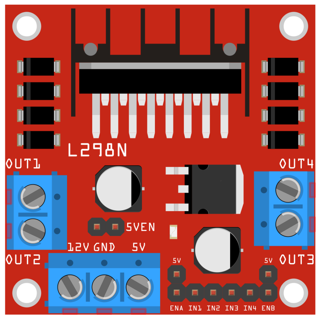
L298N Motor Driver Pinout and Working Explanation
| Pin Name | Description |
|---|---|
| ENA | Enables Motor A (PWM input to control speed) |
| IN1 | Motor A Direction Control (Input 1) |
| IN2 | Motor A Direction Control (Input 2) |
| ENB | Enables Motor B (PWM input to control speed) |
| IN3 | Motor B Direction Control (Input 3) |
| IN4 | Motor B Direction Control (Input 4) |
| OUT1 | Motor A Terminal 1 |
| OUT2 | Motor A Terminal 2 |
| OUT3 | Motor B Terminal 1 |
| OUT4 | Motor B Terminal 2 |
| 12V | Motor Power Supply (5V to 35V) |
| GND | Ground |
| 5V | Output 5V (for Arduino power if needed) |
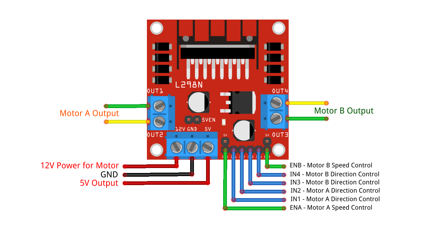
Detailed Description of Pin Working
- ENA and ENB (Enable Pins):
- Used to enable or disable motors A and B.
- Can be connected to PWM pins on the Arduino for speed control.
- PWM allows controlling the speed of the motors by adjusting the duty cycle (0 to 255).
- IN1, IN2 (Motor A Direction):
- Control the direction of Motor A.
- IN1 HIGH + IN2 LOW -> Motor A moves forward
- IN1 LOW + IN2 HIGH -> Motor A moves backward
- IN1 LOW + IN2 LOW -> Motor A stops
- IN3, IN4 (Motor B Direction):
- Control the direction of Motor B.
- IN3 HIGH + IN4 LOW -> Motor B moves forward
- IN3 LOW + IN4 HIGH -> Motor B moves backward
- IN3 LOW + IN4 LOW -> Motor B stops
- OUT1, OUT2 (Motor A Outputs):
- Connected to the terminals of Motor A.
- OUT3, OUT4 (Motor B Outputs):
- Connected to the terminals of Motor B.
- 12V:
- Power supply for motors (e.g., battery, adapter).
- Supports voltage from 5V to 35V depending on motor specifications.
- GND:
- Ground connection.
- 5V:
- Provides 5V output when powered by 12V. Can be used to power the Arduino, but it’s safer to power Arduino separately.
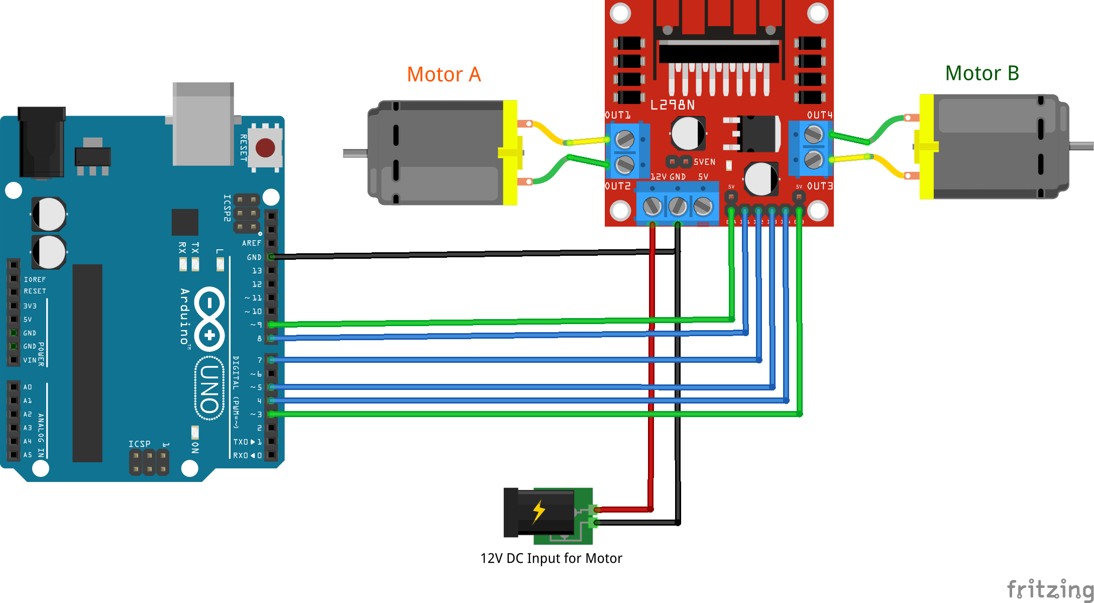
Wiring Diagram
| L298N Motor Driver | Arduino |
| ENA | 9 |
| IN1 | 8 |
| IN2 | 7 |
| ENB | 3 |
| IN3 | 5 |
| IN4 | 4 |
| 12V | External Power Supply |
| GND | GND |
| OUT1, OUT2 | Motor A Terminals |
| OUT3, OUT4 | Motor B Terminals |
Basic Code to Control Motors
This code controls two DC motors using the L298N motor driver.
// Define motor control pins for L298N Motor Driver
#define ENA 9  // Enable pin for Motor A (PWM speed control)
#define IN1 8  // Input 1 for Motor A (Direction control)
#define IN2 7  // Input 2 for Motor A (Direction control)
#define ENB 10 // Enable pin for Motor B (PWM speed control)
#define IN3 6  // Input 3 for Motor B (Direction control)
#define IN4 5  // Input 4 for Motor B (Direction control)

void setup() {
    // Set all motor driver control pins as outputs
    pinMode(ENA, OUTPUT);
    pinMode(IN1, OUTPUT);
    pinMode(IN2, OUTPUT);
    pinMode(ENB, OUTPUT);
    pinMode(IN3, OUTPUT);
    pinMode(IN4, OUTPUT);
}

void loop() {
    // Move Forward - Both motors rotate in the same direction
    digitalWrite(IN1, HIGH); // Motor A: IN1 HIGH, IN2 LOW -> Forward
    digitalWrite(IN2, LOW);
    digitalWrite(IN3, HIGH); // Motor B: IN3 HIGH, IN4 LOW -> Forward
    digitalWrite(IN4, LOW);
    analogWrite(ENA, 150); // Set Motor A speed (PWM: 0-255)
    analogWrite(ENB, 150); // Set Motor B speed (PWM: 0-255)
    delay(2000); // Move forward for 2 seconds

    // Move Backward - Both motors rotate in the opposite direction
    digitalWrite(IN1, LOW); // Motor A: IN1 LOW, IN2 HIGH -> Backward
    digitalWrite(IN2, HIGH);
    digitalWrite(IN3, LOW); // Motor B: IN3 LOW, IN4 HIGH -> Backward
    digitalWrite(IN4, HIGH);
    analogWrite(ENA, 150); // Set Motor A speed (PWM: 0-255)
    analogWrite(ENB, 150); // Set Motor B speed (PWM: 0-255)
    delay(2000); // Move backward for 2 seconds

    // Stop - Both motors stop
    digitalWrite(IN1, LOW); // Motor A: IN1 LOW, IN2 LOW -> Stop
    digitalWrite(IN2, LOW);
    digitalWrite(IN3, LOW); // Motor B: IN3 LOW, IN4 LOW -> Stop
    digitalWrite(IN4, LOW);
    delay(2000); // Stay stopped for 2 seconds
}
What to Expect from the Code
The following code will control Motor A:
- It will move forward for 3 seconds.
- It will then stop for 2 seconds.
- It will move backward for 3 seconds.
- It will stop again for 2 seconds.
This cycle will repeat continuously. You can modify the delays and motor speed according to your needs.
Speed Control Using PWM
The ENA and ENB pins control motor speed using PWM signals (values between 0 and 255). A higher value means higher speed.
analogWrite(ENA, 100); // Motor A at low speed
analogWrite(ENA, 255); // Motor A at full speedApplications and Project Ideas
- Robotic Cars – Control a two-wheeled robot or car.
- Conveyor Belts – Drive motors in industrial conveyor systems.
- Smart Home Automation – Automated window openers, curtains, etc.
- Tank Robots – Differential drive systems.
Project Ideas:
- Obstacle Avoiding Robot – Integrate with ultrasonic sensors.
- Line Following Robot – Control motor speeds based on sensor data.
- Bluetooth Car – Control motors wirelessly using Bluetooth and a smartphone app.
- DIY Conveyor System – Small conveyor belt for DIY automation.
- Autonomous Edge-Detection Robot:
Troubleshooting Tips
- Motor Not Moving: Check power supply, motor wiring, and connections.
- Overheating: Ensure the motor voltage and current are within the module’s limits.
- Low Power: Use an external power supply for motors; avoid powering motors from the Arduino.
Conclusion
The L298N motor driver with Arduino is a versatile and cost-effective solution for controlling DC motors. Whether you’re building a robot or automating a system, the L298N module provides an easy and efficient way to control motor direction and speed.
Do you have questions? Let us know in the comments! 🚀
Useful Links
Check out these helpful resources to learn more:
Related Guides/Projects:
- Autonomous Edge-Detection Robot with Arduino – Build a smart robot that avoids falling off edges.
- Ultrasonic Sensor HC-SR04 with Arduino – Measure distance and detect obstacles using an ultrasonic sensor.
External Resources:
- Arduino PWM Basics – Official guide on PWM.
- L298N Datasheet – Full specifications of the L298N Motor Driver.