
Introduction
In this tutorial we will see how to use LDR with Arduino to detect light intensity and to trigger actions based on light intensity. The light dependent resistor (LDR) (also referred to as Photoresistor) is a simple and powerful sensor that changes its resistance when exposed to light. When connecting it with Arduino we can do different projects like smart light, security systems and energy saving applications.
What you will learn in this tutorial:
- How to connect a Light Sensor LDR with Arduino using a simple voltage divider circuit.
- How to read light intensity using Arduino’s analog input.
- How to display light sensor readings on the Serial Monitor.
- How to use the LDR’s output to control other components, such as an LED.
How a Light Dependent Resistor (LDR) works:
An LDR (Light Dependent Resistor) is a variable resistor whose resistance decreases in bright light and increases in darkness. When used in a voltage divider circuit, it generates an analog voltage that an Arduino can read to determine light intensity.

What is Voltage divider:
A voltage divider is a simple circuit used to generate a voltage lower than the supply voltage. It consists of two resistors in series and output voltage is taken from the middle junction.

The formula for voltage divider is:

Where:
- Vout is the output voltage (which Arduino reads).
- Vin is the supply voltage (5v).
- R1 is the first resistor (fixed resistor).
- R2 is the second resistor (LDR, whose resistance change based on light).
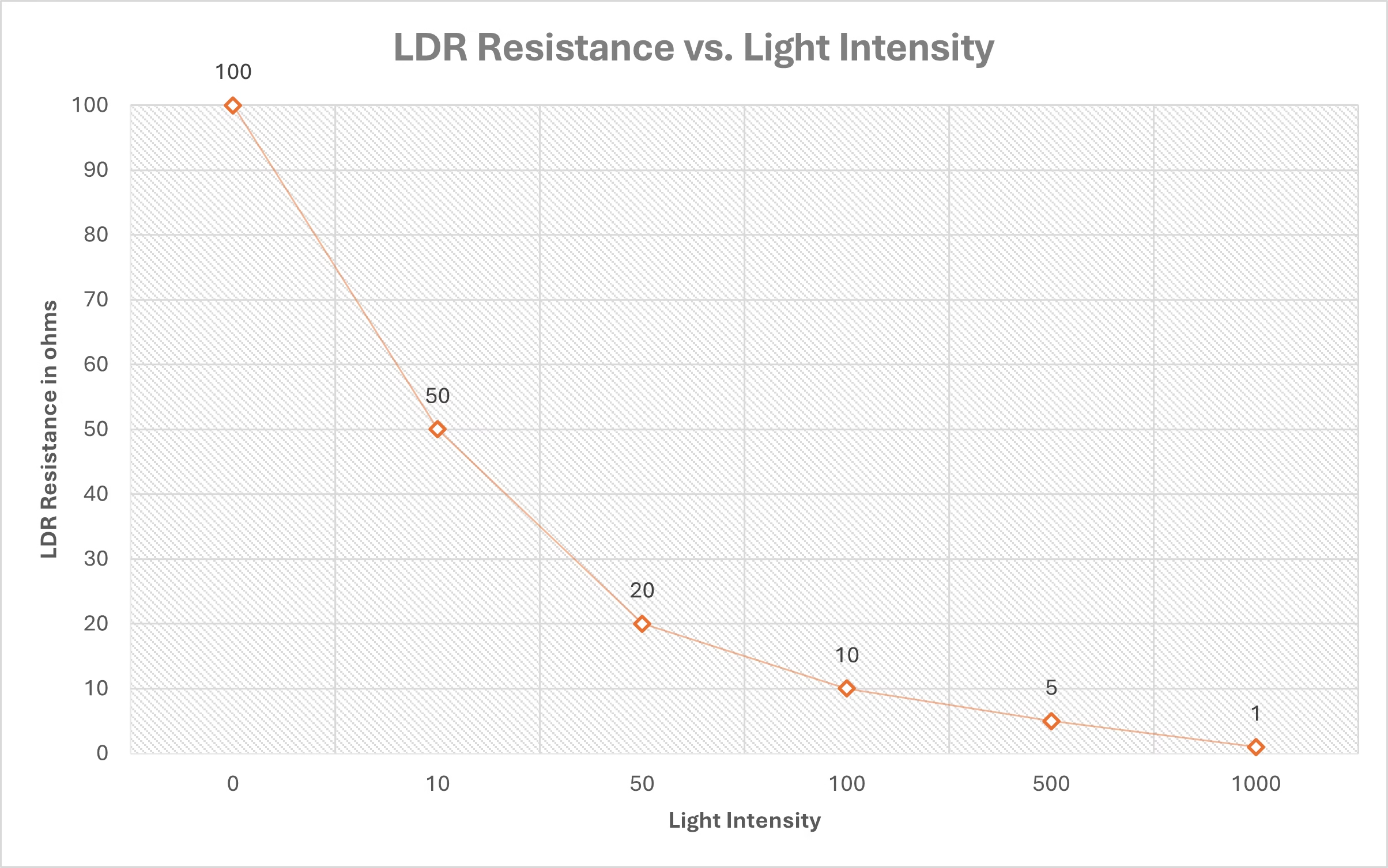
How LDR changes resistance based on light:
Resistance of LDR is inversely proportional to light intensity.
- Bright light means lower resistance (1kΩ or less).
- Darkness means higher resistance (100kΩ or more).
The given equation tells us the behavior:

Where:
- Rdark is the LDR resistance in complete darkness.
- L is the light intensity.
- Y is the material dependent constant.
How the LDR voltage output changes:
When light intensity increases:
- LDR resistance decreases, it means Vout is lower (close to 0V).
- Arduino reads a LOW analog value (near 0).
When light intensity decreases:
- LDR resistance increases then 𝑉out increases (closer to 5V).
- Arduino reads a HIGH analog value (near 1023).
Choosing the right resistor
To create an effective voltage divider, we need to select an appropriate fixed resistor (R1). A 10kΩ resistor is commonly used but you can adjust it based on your application.
For low light detection use a higher values resistance like 47kΩ.
For bright light detection use a lower value resistance like 4.7kΩ.
Formula for the output voltage at A0:

When light increases then RLDR decreases, it makes VAo lower.
When light decreases then RLDR increases, it makes VAo higher.
Components required:
- Arduino (UNO, MEGA etc.)
- Light Dependent Resistor (LDR)
- 10kΩ resistor
- Bread Board
- Jumper wires
- USB Cable for Arduino
Wiring the LDR with Arduino:
- Connect one leg of the LDR into the 5v pin of Arduino.
- Connect the other leg of the LDR to 10kΩ resistor then to A0(analog pin) of the Arduino.
- Connect the other leg of the 10kΩ resistor to the GND (ground) pin of the Arduino.
| LDR | Arduino |
| First Leg | 5v |
| Second Leg | 10kΩ resistor + A0 |
| 10kΩ Second Leg | GND |

Code for LDR with Arduino:
int ldrPin = A0;  // LDR connected to A0
int ldrValue;     // Variable to store light value

void setup() {
  Serial.begin(9600);  // Start serial communication
}

void loop() {
  ldrValue = analogRead(ldrPin);  // Read the LDR value
  Serial.print("Light Intensity: ");
  Serial.println(ldrValue);  // Print value to Serial Monitor

  delay(500);  // Wait for half a second
}
Explanation:
ldrpin = A0: The LDR is connected to the analog pin A0 on the Arduino.ldrvalue: This variable will store the analog value that LDR reads.Serial.begin(9600): It initializes serial communication at a baud rate of 9600(data transfer speed). It allows us to send data to serial monitor so we can see the LDR readings.analogRead(ldrpin): It reads the analog voltage from A0 pin ranging from 0 to 1023. Bright light means higher value which is closer to 1023, and Dim light means Lower value which is closer to 0.Serial.print(“Light Intensity”): It prints a Label Light Intensity before the value.Serial.print(“ldrvalue”): It will print the actual value of Light intensity.delay (500): Wait 0.5 seconds then read the value again.
Example: Automatic LED based on Light
In this example we will use an LDR to automatically control an LED based on ambient light levels. Arduino will continuously monitor the light intensity, and when it drops below a certain threshold the LED will turn ON and when there is sufficient light the LED will turn OFF.
By using this setup, we can make applications like automatic night lamps, automatic streetlights or smart lighting systems.
Components Required:
- LED
- 220Ω Resistor
Circuit diagram:
- LDR circuit will remain the same.
- Connect the positive side of the LED (long leg) to the digital pin 9 of Arduino.
- Connect the negative side of the LED (Short leg) to the GND pin through a 220Ω resistor.
| LED | Arduino |
| Anode | D9 |
| Cathode | 220Ω resistor then GND |

Arduino Code to control the LED using LDR:
int ldrpin = A0; //LDR connectod to A0
int ledpin = 9;
int ldrvalue;  // Funtion to store LDR value
int thershold = 600;

void setup() {
  pinMode(ledpin,OUTPUT);
  Serial.begin(9600);  //Start serial communation
}

void loop() {
  ldrvalue = analogRead(ldrpin);
  Serial.print("Light Intensity");
  Serial.print(ldrvalue);

  if (ldrvalue<thershold)  //Check if its dark or not
  {
    digitalWrite(ledpin,HIGH); //Turn on the LED
  }
  else{
    digitalWrite(ledpin,LOW);  //Turn off the LED
  }

  delay(500);
}
Explanation:
Declaring Variables and Pins:
ldrpin: stores the pin where the LDR is connected.ledpin: is assigned to pin 9, where the LED is connected.ldrvalue: will store the sensor’s reading from the LDR.- threshold is set to 600, meaning if the light intensity falls below this value, the LED will turn ON.
Setup Function:
pinMode(ledpin, OUTPUT): Configures the LED pin as an output.Serial.begin(9600): Initializes serial communication to monitor sensor values.
Loop Function:
analogRead(ldrpin): Reads the voltage from the LDR sensor and stores it in ldrvalue.Serial.print("Light Intensity: "); Serial.println(ldrvalue): Prints the light intensity to the Serial Monitor for real-time monitoring.
Decision Making:
- If
ldrvalueis below threshold (dark environment), the LED turns ON (HIGH). - If
ldrvalueis above threshold (bright environment), the LED turns OFF (LOW). delay(500);→ Waits 500ms before repeating the loop.
Practical Applications
- Automatic Night Lamps
- Street Lighting Systems
- Smart Home Application
If you want to control high-voltage devices like bulbs or fans based on ambient light, check out how to use a relay module with Arduino for switching.
To combine light sensing with motion detection, you can also learn how to use a PIR sensor with Arduino for creating motion-activated lighting systems.
Conclusion
Using an LDR with Arduino is a simple and powerful way to detect light and automate task like turning on/off. We can extend this project by adding relays to control AC appliances, adding an LCD for display or connecting it with IoT platforms
If you find this tutorial helpful share it with others and explore our other Arduino guides for more exciting projects
If you have any questions or need additional help, feel free to ask in the comments.
Thank You