Introduction
This article provides a detailed technical reference of the ESP32 pinout, focusing on GPIO characteristics, peripheral functionality, and pin constraints relevant for robust embedded system design. The ESP32 by Espressif Systems is a high-performance SoC with integrated Wi-Fi and Bluetooth, dual-core Tensilica LX6 processors, and a comprehensive set of peripherals.
The ESP32 family consists of multiple variants designed for different performance levels, memory configurations, and connectivity options. Espressif Systems has developed a range of modules and SoCs under the ESP32 umbrella, each tailored for specific applications—from basic IoT devices to AI-enabled edge computing.
Below is an overview of the most prominent ESP32 types, categorized by their features and target use cases.
| Variant | CPU | Wi-Fi | Bluetooth | USB OTG | AI Accel | RISC-V | PSRAM |
|---|---|---|---|---|---|---|---|
| WROOM-32 | Xtensa LX6 | ✅ | ✅ (v4.2) | ❌ | ❌ | ❌ | ❌ |
| WROVER | Xtensa LX6 | ✅ | ✅ | ❌ | ❌ | ❌ | ✅ |
| ESP32-S2 | Xtensa LX7 | ✅ | ❌ | ✅ | ❌ | ❌ | ❌ |
| ESP32-S3 | Xtensa LX7 | ✅ | ✅ (v5.0) | ✅ | ✅ | ❌ | ✅ |
| ESP32-C3 | RISC-V | ✅ | ✅ (v5.0) | ❌ | ❌ | ✅ | ❌ |
| ESP32-C6 | RISC-V | ✅ (Wi-Fi 6) | ✅ | ❌ | ❌ | ✅ | ❌ |
| ESP32-H2 | RISC-V | ❌ | ✅ + Zigbee | ❌ | ❌ | ✅ | ❌ |
For more ESP32 features and details, you can visit: ESP32 Wi-Fi & Bluetooth SoC | Espressif Systems
1. ESP32 Pinout General Description
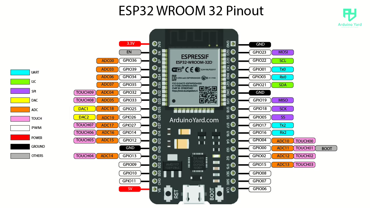
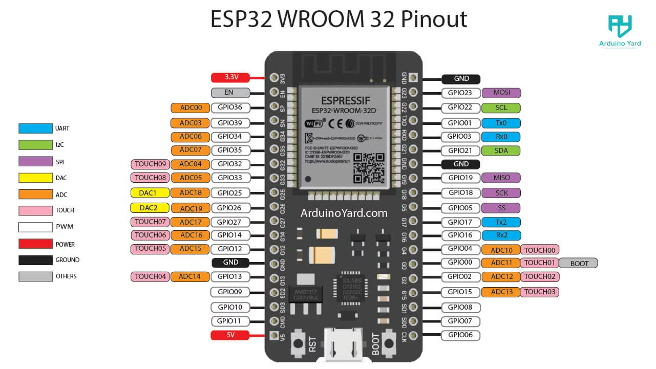
The ESP32 DevKit boards (e.g., ESP32 WROOM-32, ESP32 WROVER) typically expose 30 to 38 pins. The given ESP32 pinout description is for the ESP32 with 38 pins, including:
- Up to 34 GPIOs
- 18 ADC channels, 2 DAC outputs
- Multiple UART, SPI, I2C, and PWM capable pins
- Specialized features such as capacitive touch sensing and RTC (Real Time Clock) GPIOs for ultra-low-power applications
Refer to the annotated ESP32 pinout diagram above for physical mapping.
2. GPIO Functionality
Each GPIO pin on the ESP32 supports multiple functions via IO mux configuration. The available features per pin are defined in the ESP32 Pinout Technical Reference Manual and assigned through the GPIO Matrix.
2.1 GPIO Usage Classifications
| GPIOs | Description |
|---|---|
| 0, 2, 4, 5, 12–19, 21–23, 25–27, 32–33 | General-purpose I/O, safe to use for digital I/O |
| 6–11 | Connected to SPI flash; avoid using |
| 34–39 | Input-only, no internal pull-up/pull-down |
| 0, 2, 12 | Have bootstrapping functions during startup |
Note: GPIOs 6–11 are internally used by the SPI flash and should not be configured by the user.
3. Peripheral Function Mapping
3.1 ADC and DAC
- ADC1: GPIOs 32–39 (up to 8 channels)
- ADC2: GPIOs 0, 2, 4, 12–15, 25–27 (10 channels, but restricted when Wi-Fi is active)
- DAC: GPIO25 (DAC1), GPIO26 (DAC2)
3.2 UART
- UART0: Default TX/RX on GPIO1 and GPIO3
- UART1/UART2: Configurable via GPIO matrix, commonly on GPIO9/10 or GPIO16/17
3.3 SPI/I2C
- Up to 4 SPI interfaces available
- VSPI: GPIO23 (MOSI), GPIO19 (MISO), GPIO18 (SCK), GPIO05 (SS)
- I2C can be mapped to almost any GPIO; commonly GPIO21 (SDA), GPIO22 (SCL)
3.4 PWM (LEDC)
All GPIOs (except input-only ones) support PWM output via the LEDC module. Up to 16 independent channels are available.
3.5 Touch Sensors
Available on GPIOs: 0, 2, 4, 12–15, 27, 32, 33
4. Bootstrapping Pins and Cautions
The ESP32 uses several pins to configure boot modes:
| GPIO | Bootstrapping Role | Notes |
|---|---|---|
| GPIO0 | Must be LOW to enter UART bootloader mode | Pull-up resistor recommended |
| GPIO2 | Must be LOW at boot for correct mode | Usually tied to internal functions (LED, etc.) |
| GPIO12 | Controls flash voltage; must be LOW at boot | Avoid using unless understood |
5. Power Pins and Reference Voltages
| Pin | Function |
|---|---|
| 3V3 | Regulated 3.3V output |
| GND | Ground |
| VIN | Input voltage (5V via USB) |
| EN | Enable pin; pull high to enable ESP32 |
Ensure all connected peripherals operate within the ESP32’s 3.3V logic level. Using 5V signals without proper level shifting can damage the chip. The maximum voltage for the ESP32’s Vin pin is 5V. It is recommended to keep the input voltage around 6 or 7 Volts to avoid excessive power loss as heat on the voltage regulator.
6. Best Practices
- Use GPIO matrix and
gpio_matrix_in/outAPIs for custom peripheral remapping. - Leverage RTC GPIOs (e.g., GPIOs 0, 2, 4, 12–15, 25–27, 32–39) for wakeup from deep sleep.
- Always consider electrical constraints: input-only pins, boot strapping logic levels, and internal pull resistor availability.
- Avoid using ADC2 channels when Wi-Fi is active due to peripheral conflict.
Conclusion
Understanding the ESP32 pinout is critical for stable and scalable embedded development. By carefully selecting GPIOs and observing boot behavior constraints, developers can fully utilize the ESP32’s powerful I/O capabilities across diverse applications—from real-time control to low-power IoT.
Here is how to get started with ESP32 in arduino IDE:
How To Install ESP32 And ESP8266 Boards In Arduino IDE (Step-by-Step Guide) – ArduinoYard
Very usefull page, with a compréhensive coverage.
At the beginning it is stated :
“Up to 34 GPIOs and 18 ADC channels”,
How can these be accessed simultaneously (if possible le ?)
Hi, thanks for visiting the website. what do you mean by accessing simultaneously?