
Introduction
MAX9814 with Arduino is a powerful combination for audio-related projects that need precise and amplified sound detection. Whether you’re working on voice-activated devices, audio-reactive lighting, or DIY sound meters, the MAX9814 microphone amplifier module offers great performance with automatic gain control (AGC).
In this guide, we’ll explore what the MAX9814 module is, how it works, how to connect it to an Arduino, and provide example code to get you started. We’ll also highlight key differences between MAX9814 and basic sound sensors, and suggest project ideas where it shines.
What is the MAX9814 Microphone Amplifier?
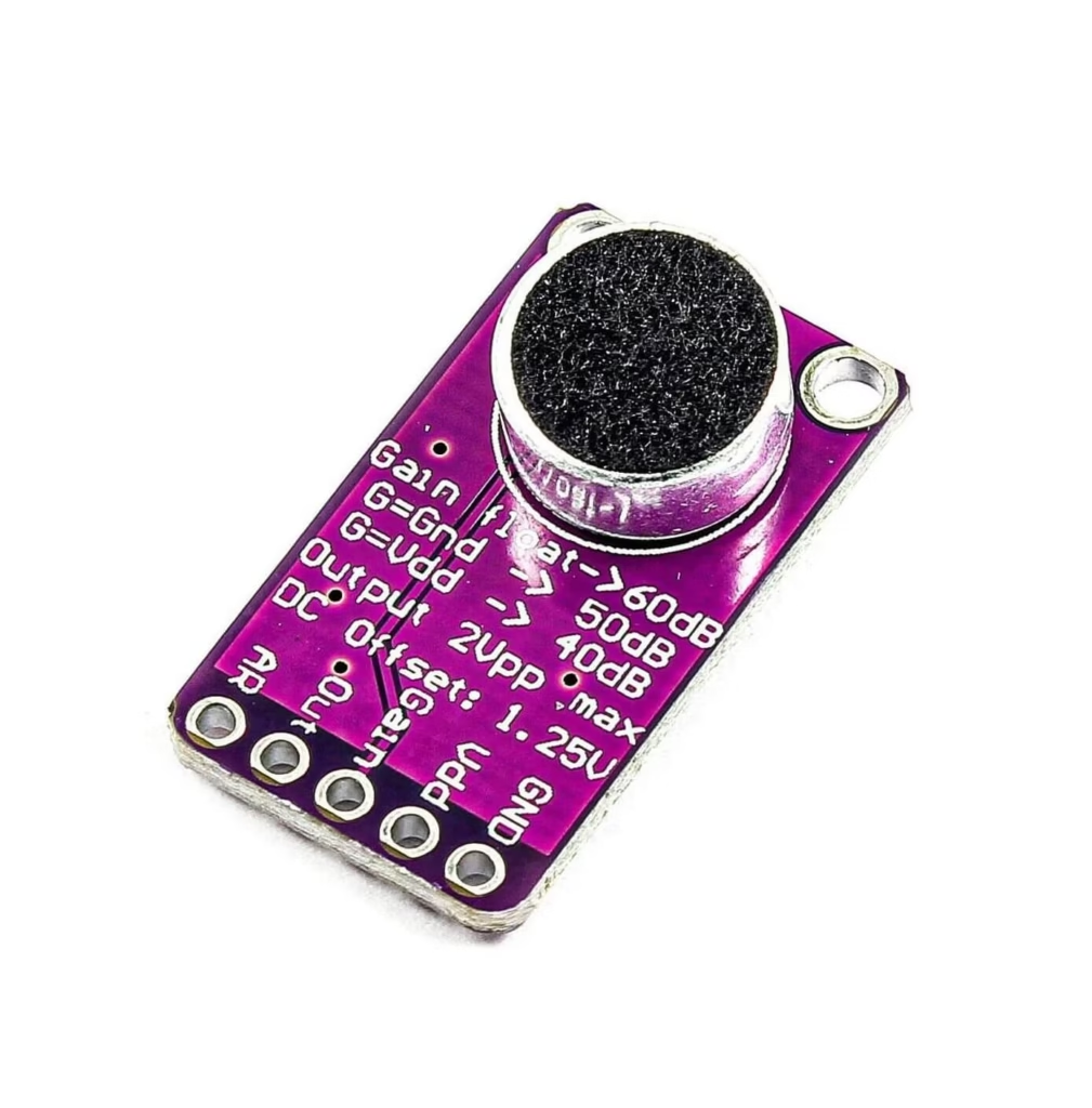
The Adafruit MAX9814 is a high-performance microphone amplifier module that uses an electret microphone and the MAX9814 IC. It includes built-in Automatic Gain Control (AGC), which allows it to dynamically adjust amplification levels depending on the loudness of the sound, making it ideal for environments with variable noise levels.
Key Features:
- Built-in electret microphone
- Low noise amplifier
- Automatic Gain Control (AGC)
- Configurable gain and attack/release time
- Operating Voltage: 2.7V to 5.5V
- Analog output
Use case: Voice detection, sound level monitoring, audio visualization, and other sensitive audio input applications.
Max9814 Pinout and Configuration
Here’s a quick reference of the Max9814 module pinout:
| Pin | Description |
|---|---|
| VDD | Power supply (2.7V–5.5V, typically 3.3V or 5V) |
| GND | Ground |
| OUT | Analog audio output |
| AR | Attack/Release control (for AGC timing) |
| Gain | Selects fixed gain (default 40dB) |
| VDD (MIC) | Internal connection to power mic bias |
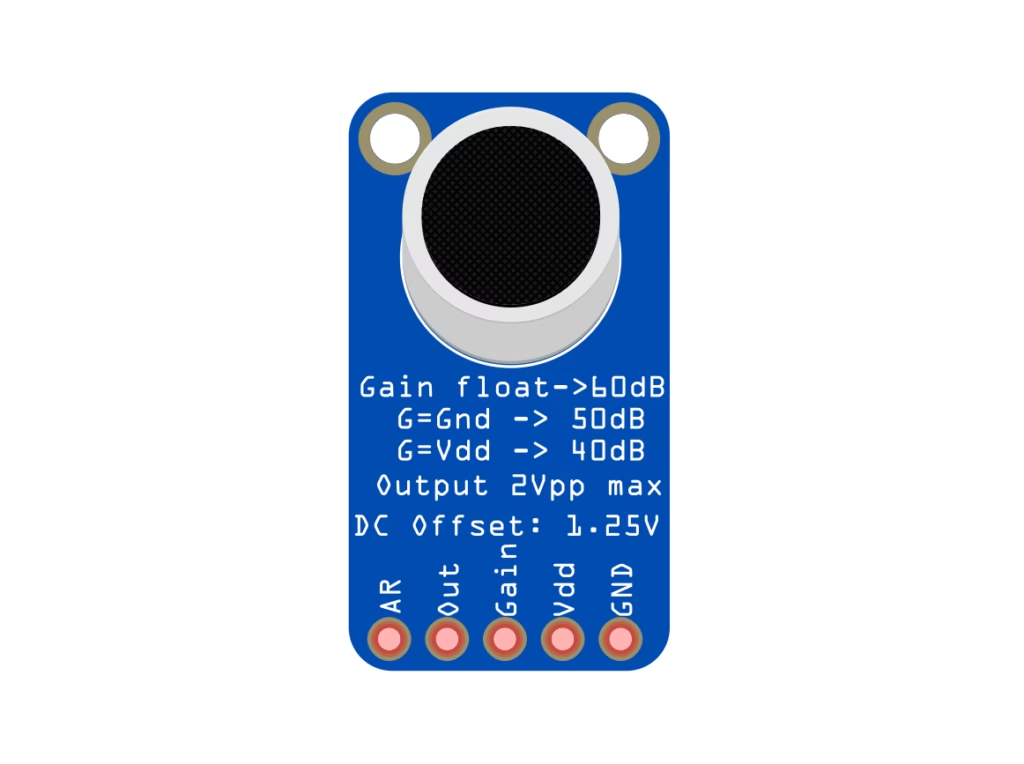
AGC and Gain Settings:
- You can change the AGC response time by connecting AR to GND or VDD.
- The gain pin allows selecting 40dB, 50dB, or 60dB gain via resistor pull-downs.
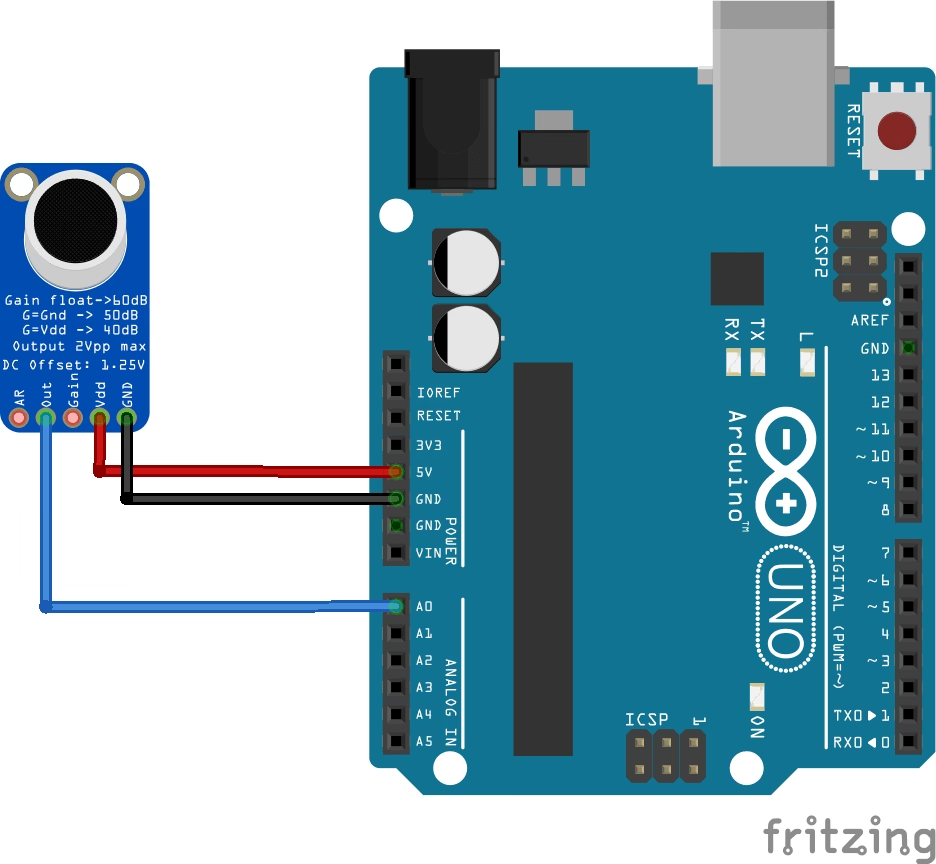
Connecting MAX9814 with Arduino
Here’s how to connect the MAX9814 to an Arduino Uno for analog audio level reading:
| MAX9814 Pin | Arduino Uno Pin |
| VDD | 5V |
| GND | GND |
| OUT | A0 |
| AR, Gain | Leave unconnected (use default AGC & gain) |
Example Arduino Code: Audio Level Reader
const int micPin = A0; // Analog pin for MAX9814 output
void setup() {
Serial.begin(9600);
}
void loop() {
int micValue = analogRead(micPin);
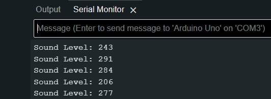
Serial.print("Sound Level: ");
Serial.println(micValue);
delay(50);
}
This basic code reads analog values from the MAX9814 output. You can use this data to build a real-time sound meter or trigger audio-reactive behavior.
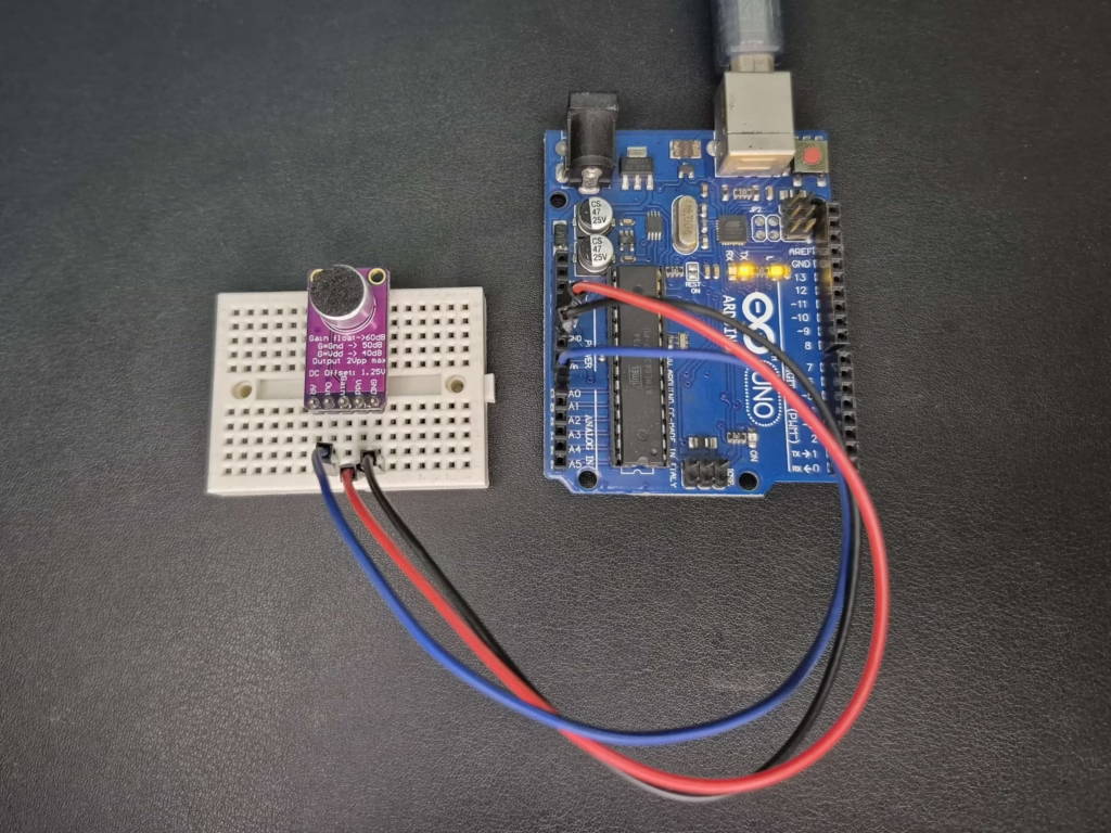
Hardware Setup:
Serial Monitor Output:
Applications of Max9814 with Arduino
- Voice-activated switches and assistants
- Audio visualizers and VU meters
- Sound-level logging for environmental noise
- Home automation triggered by sound
- DIY voice-controlled robots
Why Use Max9814 Over Basic Sound Sensors?
| Feature | MAX9814 Module | Basic Sound Sensor |
| Audio Output | Analog (clean, amplified) | Analog/Digital (noisy) |
| AGC Support | Yes | No |
| Sensitivity | High | Low to Medium |
| Audio Signal Quality | Excellent | Poor to Average |
| Price | Slightly higher | Very affordable |
The MAX9814 is ideal when you need reliable, high-quality audio input or cleaner analog readings.
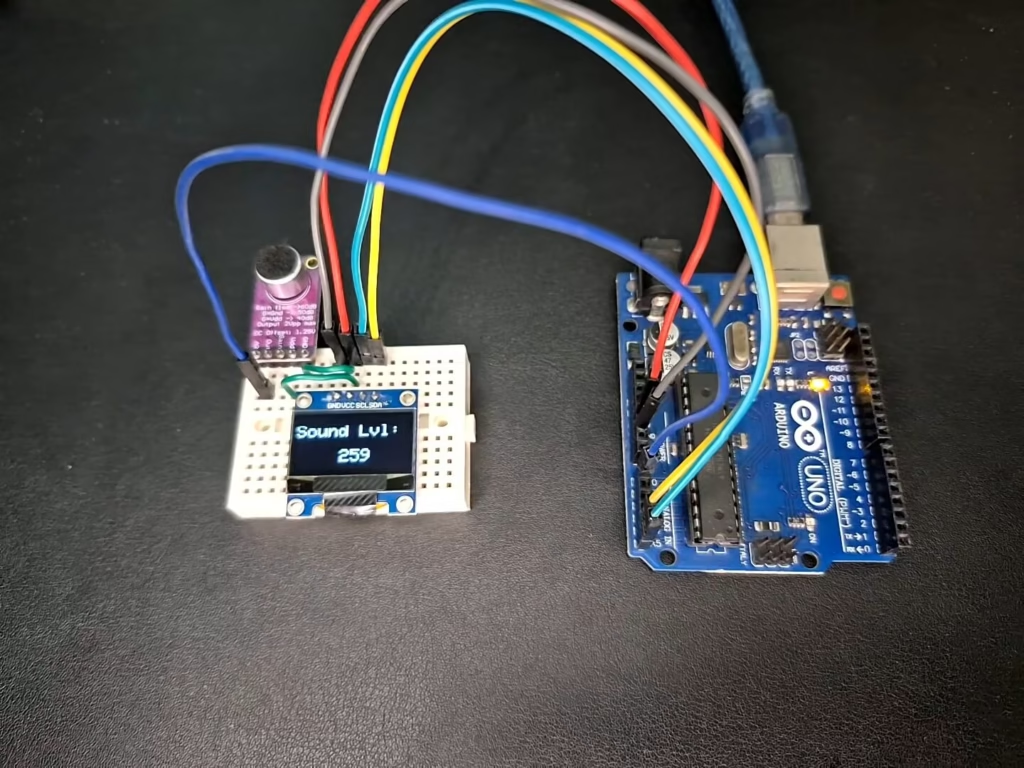
Project Idea: Sound Level Meter with OLED Display
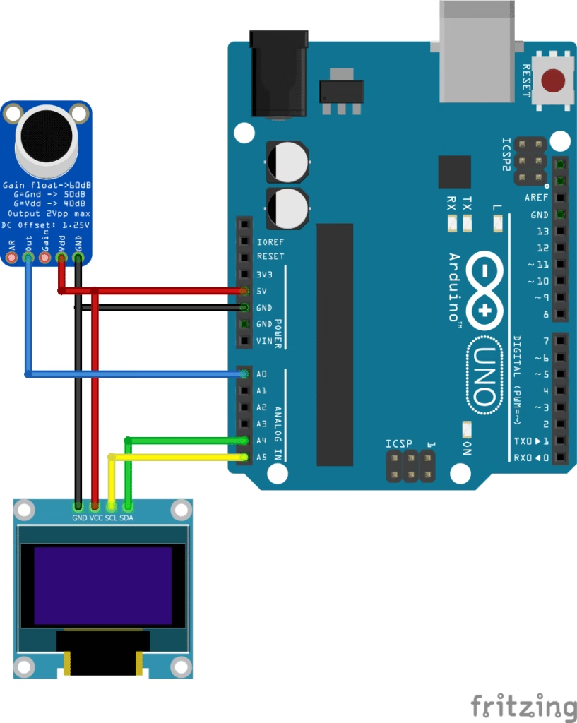
Use the MAX9814 module with an I2C OLED display (e.g., SSD1306) to create a real-time audio level meter.
Wiring Overview:
- MAX9814 → Arduino A0
- OLED Display → SDA to A4, SCL to A5
Libraries Needed:
- Adafruit_GFX
- Adafruit_SSD1306
Code Snippet:
#include <Adafruit_GFX.h>
#include <Adafruit_SSD1306.h>

#define SCREEN_WIDTH 128
#define SCREEN_HEIGHT 64
#define OLED_RESET -1
Adafruit_SSD1306 display(SCREEN_WIDTH, SCREEN_HEIGHT, &Wire, OLED_RESET);

int micPin = A0;

void setup() {
  display.begin(SSD1306_SWITCHCAPVCC, 0x3C);
  display.clearDisplay();
  display.setTextSize(1);
  display.setTextColor(SSD1306_WHITE);
}

void loop() {
  int micVal = analogRead(micPin);
  display.clearDisplay();
  display.setTextColor(WHITE);
  display.setTextSize(2);
  display.setCursor(0, 10);
  display.print("Sound Lvl:");
  display.setCursor(50, 40);
  display.print(micVal);
  display.display();
  delay(100);
}
Demo:
Conclusion
If you’re looking for a high-quality audio input module, combining MAX9814 with Arduino provides a simple yet powerful solution. Its AGC, adjustable gain, and clean output make it superior to basic sound sensors for many applications. Start with simple sound level monitoring, then expand into voice-activated or reactive projects for real-world interaction.
💡 Note: This tutorial is based on practical testing and usage of the MAX9814 with Arduino. For in-depth technical details about the internal working of the AGC (Automatic Gain Control) and configuration options, you can refer to the official Adafruit MAX9814 Microphone Amplifier Guide.
Related Tutorials
If you’re interested in learning more about sound detection or visual displays, check out these related tutorials on ArduinoYard:
- 🔊 Sound Sensor with Arduino: Build Sound-Reactive Projects – Explore how to detect claps or loud noises using a basic sound sensor module. Great for simpler audio projects or comparisons with the MAX9814.
- 🖥️ I2C OLED Display with Arduino – Learn how to interface I2C OLED screens with Arduino to visualize data, like sound levels from the Max9814 module.