Introduction
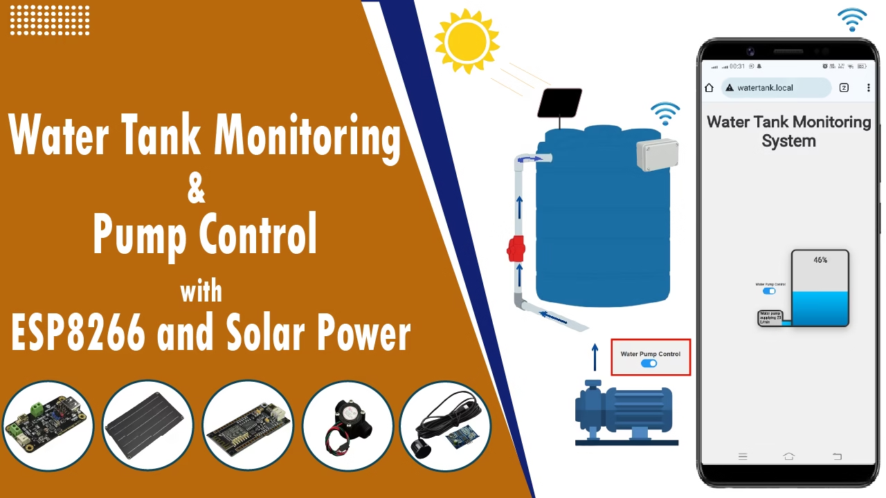
Water is one of the most essential resources, yet its management often remains inefficient. To address this, we introduce an IoT-Based Water Tank Monitoring and Pump Control System using ESP8266 and Solar Power. This advanced system provides real-time monitoring of water levels and flow rates, along with manual pump control via a web-based interface. Users can remotely turn the pump ON or OFF from any device connected to the network, offering convenient control and better management. Powered by solar energy, the system is cost-effective, environmentally friendly, and suitable for homes, farms, and remote locations. With smart monitoring and remote control, you can optimize water usage and contribute to sustainable water management.
Watch the Part 1 on YouTube.
If you haven’t seen Part 1, where we covered the basic water level and flow monitoring system, check out “IoT-Based Water Tank Monitoring System – Part 1” for the complete foundation.
Project Overview
The IoT-Based Water Tank Monitoring and Pump Control System is designed to:
- Monitor the water level in a tank using an ultrasonic sensor.
- Measure the water flow rate using a flow sensor.
- Display real-time data on a web interface hosted by the ESP8266 microcontroller.
- Allow manual pump control via the web interface, enabling users to remotely turn the pump ON or OFF.
- Operate on solar power, making it suitable for remote locations and off-grid setups.
This combination of monitoring, control, and renewable power makes the system ideal for smart water management in homes, farms, and industrial applications.
Components Used
- FireBeetle ESP8266 IoT Microcontroller
- Product Link
- A low-power microcontroller with Wi-Fi capability, ideal for IoT projects.
- Alternatively you can use any other ESP8266 microcontroller like NodeMCU, D1 Mini, or any other ESP8266-based boards.
- You can also use an ESP32 (just update the pins used in the code).
- Solar Power Manager 5V
- Product Link
- Manages solar power input and provides stable 5V output for connected devices.
- Monocrystalline Solar Panel (5V 1A)
- Product Link
- Efficient solar panel to power the system.
- Water Flow Sensor YF-S201
- Product Link
- Measures the flow rate of water in liters per minute.
- Waterproof Ultrasonic Distance Sensor JSN-SR04T
- Product Link
- Measures the distance between the sensor and the water surface.
- Relay Module (Single Channel)
- Product Link
- Used to control the water pump based on user commands from the web interface.
- Water Pump (AC or DC, depending on system design)
- The pump that controls water flow into or out of the tank, activated manually through the web interface.
- 3.7V Lithium-ion Battery
- Provides backup power for the system, ensuring uninterrupted operation.
- Weatherproof Box
- Protects the components from environmental elements.
- Jumper Wires
- For electrical connections between components.
Hardware Setup
Wiring Diagram
Below is the wiring diagram for the project. Follow it to ensure accurate connections between the components.
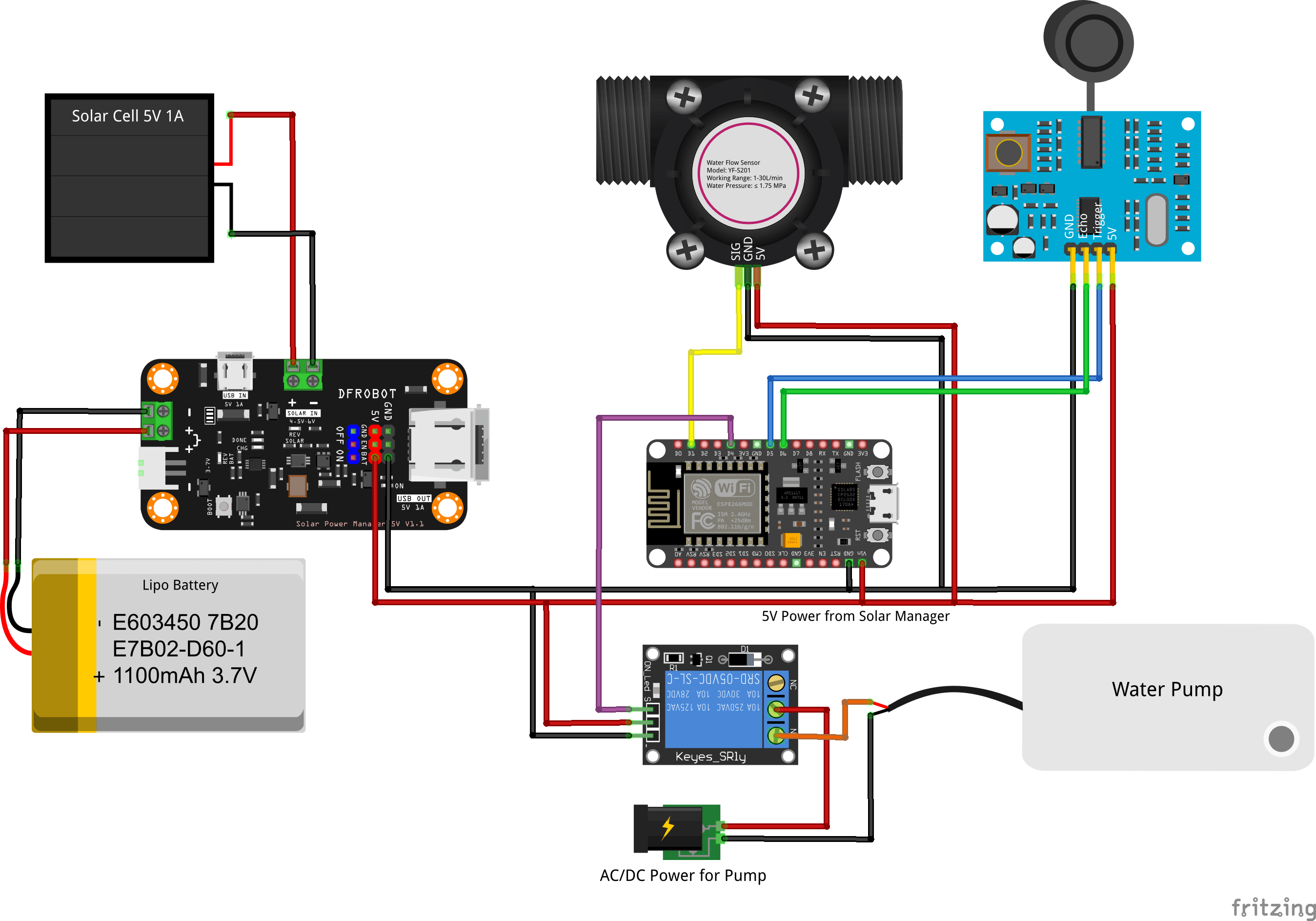
Connecting the Sensors
- Ultrasonic Sensor (JSN-SR04T):
- Connect the Trig pin to
D5. - Connect the Echo pin to
D6.
- Connect the Trig pin to
- Flow Sensor (YF-S201):
- Connect the signal pin to
D1.
- Connect the signal pin to
- Relay Module (for Pump Control)
- Connect the signal pin to D4.
- Water Pump
- Connect the pump to the relay’s normally open (NO) contacts, allowing the ESP8266 to control power to the pump.
- Use a separate power source (DC or AC depending on your pump) if needed, and ensure the relay is rated for the pump’s voltage and current.
Power Management
- Use the Solar Power Manager to regulate the power from the solar panel.
- Connect the output of the power manager to the ESP8266.
- Connect the 3.7V Lithium-ion battery to the Solar Power Manager for backup power.
Housing the Components
- Place all components inside a weatherproof box to ensure durability.
Mounting the Sensors
- Position the ultrasonic sensor above the water tank.
- Install the flow sensor on the inlet pipeline for accurate water flow measurement.
Software Setup
Arduino Code
The provided code, written for the Arduino IDE, uses libraries for Wi-Fi and web server functionality. Key features include:
- Ultrasonic Sensor: Measures water level and converts it to a percentage based on distance.
- Flow Sensor: Calculates water flow rate in liters per minute using pulse counting.
- Relay Module: Controls the water pump based on manual commands from the web interface.
- Web Interface: Displays real-time water level and flow rate on a local webpage via an ESP8266-hosted asynchronous web server.
// IoT-Based Water Tank Monitoring + Pump Control with ESP8266 and Solar Power - Part 2
#ifdef ESP32
#include "WiFi.h"
#include <SPIFFS.h>
#include <ESPmDNS.h>
#else
#include "ESP8266WiFi.h"
#include <FS.h>
#include <ESP8266mDNS.h>
#endif

#include "ESPAsyncWebServer.h"
#include <movingAvg.h>

// Moving average filters for ultrasonic sensor and flow sensor readings
movingAvg distanceAvg(10);
movingAvg frAvg(10);

// Pin assignments for sensors and pump
const int trigPin = D5;        // Ultrasonic sensor trigger pin
const int echoPin = D6;        // Ultrasonic sensor echo pin
const int flowSensorPin = A0;  // Flow sensor signal pin
const int pumpPin = D4;        // Pump relay control pin

// Flow sensor calibration factor (adjust for your sensor)
float CalibrationFactor = 7.5;

// Distance thresholds (in cm) for water level detection
int minHeight = 25;   // Distance from sensor to water surface when tank is full
int maxHeight = 115;  // Distance from sensor to tank bottom (empty tank)

// WiFi credentials
const char* ssid = "YourSSID";           // Replace with your Wi-Fi SSID
const char* password = "YourPassword";   // Replace with your Wi-Fi password

// Create web server object on port 80
AsyncWebServer server(80);

// Variables for flow rate calculation
volatile int pulseCount = 0;      // Pulse count from flow sensor
float flowRate = 0.0;              // Calculated flow rate
unsigned long oldTime = 0;         // Timer for flow rate calculation
unsigned long readingInterval = millis(); // Timer for sensor readings

int percentage;  // Water level in percentage
float dAvg;      // Smoothed distance value (moving average)

// Store current pump state (on/off)
bool pumpState = false;

// Placeholder processor (for future HTML template processing if needed)
String processor(const String& var) {
  return String();
}

// ISR for flow sensor pulse counting (called on each falling pulse)
ICACHE_RAM_ATTR void pulseCounter() {
  pulseCount++;
}

void setup() {
  Serial.begin(115200);

  // Initialize SPIFFS for serving HTML, CSS, and JS files
  if (!SPIFFS.begin()) {
    Serial.println("Error mounting SPIFFS");
  }

  // Set pump control pin as output and turn it off initially
  pinMode(pumpPin, OUTPUT);
  digitalWrite(pumpPin, LOW);

  // Initialize moving average filters
  distanceAvg.begin();
  frAvg.begin();

  // Connect to WiFi
  WiFi.begin(ssid, password);
  Serial.print("Connecting");
  while (WiFi.status() != WL_CONNECTED) {
    Serial.print(".");
    delay(1000);
  }
  Serial.println("Connected");

  // Start mDNS responder for local hostname (http://watertank.local)
  if (MDNS.begin("watertank")) {
    Serial.println("mDNS responder started");
  }

  // Configure ultrasonic sensor pins
  pinMode(trigPin, OUTPUT);
  pinMode(echoPin, INPUT);

  // Set flow sensor pin and attach interrupt to count pulses
  pinMode(flowSensorPin, INPUT);
  attachInterrupt(digitalPinToInterrupt(flowSensorPin), pulseCounter, FALLING);

  // Initialize timer for flow rate calculation
  oldTime = millis();

  // Define web server routes to serve files from SPIFFS
  server.on("/", HTTP_GET, [](AsyncWebServerRequest * request) {
    request->send(SPIFFS, "/index.html", String(), false, processor);
  });

  server.on("/style.css", HTTP_GET, [](AsyncWebServerRequest * request) {
    request->send(SPIFFS, "/style.css", "text/css");
  });

  server.on("/script.js", HTTP_GET, [](AsyncWebServerRequest * request) {
    request->send(SPIFFS, "/script.js", "application/javascript");
  });

  // Endpoint to get water level percentage
  server.on("/distance", HTTP_GET, [](AsyncWebServerRequest * request) {
    request->send(200, "text/plain", String(distance()));
  });

  // Endpoint to get flow rate in L/min (or your preferred unit)
  server.on("/frate", HTTP_GET, [](AsyncWebServerRequest * request) {
    request->send(200, "text/plain", flowrate());
  });

  // Endpoint to toggle pump on or off (by sending `state=on` or `state=off`)
  server.on("/pump", HTTP_GET, [](AsyncWebServerRequest * request) {
    if (request->hasParam("state")) {
      String state = request->getParam("state")->value();
      if (state == "on") {
        digitalWrite(pumpPin, HIGH); // Turn pump on
        pumpState = true;
      } else {
        digitalWrite(pumpPin, LOW); // Turn pump off
        pumpState = false;
      }
    }
    request->send(200, "text/plain", pumpState ? "on" : "off");
  });

  // Endpoint to get current pump status (returns "on" or "off")
  server.on("/pump-status", HTTP_GET, [](AsyncWebServerRequest * request) {
    request->send(200, "text/plain", pumpState ? "on" : "off");
  });

  // Start the server
  server.begin();
}

void loop() {
#ifdef ESP8266
  MDNS.update();  // Keep mDNS service running (for ESP8266 only)
#endif

  // Reconnect to WiFi if disconnected
  if (WiFi.status() != WL_CONNECTED) {
    WiFi.reconnect();
    while (WiFi.status() != WL_CONNECTED) {
      Serial.print(".");
      delay(1000);
    }
    Serial.println("Connected");
  }

  // Read sensors every second
  if ( millis() - readingInterval > 1000) {
    readingInterval = millis();
    distance();  // Read water level
    flowrate();  // Read flow rate
  }
}

// Function to read water level using ultrasonic sensor
String distance() {
  long duration;
  float distanceCm;

  // Send pulse to trigger ultrasonic sensor
  digitalWrite(trigPin, LOW);
  delayMicroseconds(2);
  digitalWrite(trigPin, HIGH);
  delayMicroseconds(10);
  digitalWrite(trigPin, LOW);

  // Measure time for echo to return
  duration = pulseIn(echoPin, HIGH);

  // Convert time to distance in cm
  distanceCm = duration * 0.034 / 2;

  // If distance is within valid range, calculate water level percentage
  if (distanceCm >= minHeight && distanceCm <= maxHeight) {
    percentage = map(distanceAvg.reading(distanceCm), minHeight, maxHeight, 0, 100);

    if (percentage < 0) percentage = 0;
    else if (percentage > 100) percentage = 100;

    // Invert percentage to get "fullness" instead of "emptiness"
    percentage = 100 - percentage;
  }

  Serial.print("Water Level: ");
  Serial.println(percentage);
  return String(percentage);
}

// Function to calculate flow rate from sensor pulses
String flowrate() {
  unsigned long currentTime = millis();
  unsigned long timeInterval = currentTime - oldTime;

  // Calculate flow rate every second
  if (timeInterval > 1000) {
    flowRate = (pulseCount / CalibrationFactor); // Calculate flow rate
    oldTime = currentTime;  // Reset timer
    pulseCount = 0;         // Reset pulse counter
  }

  float avgFlowRate = frAvg.reading(flowRate); // Apply moving average filter

  Serial.print("Flow Rate: ");
  Serial.println(avgFlowRate);

  return String(avgFlowRate);
}You can download the code and webpage design files using the button below:
Changes to Make in Code
Before uploading the provided code to your ESP8266, you’ll need to make a few adjustments to personalize it for your setup. Below are the parameters you need to modify in the code:
- Wi-Fi SSID and Password
To connect your ESP8266 to your local Wi-Fi network, replace the placeholder text with your network’s SSID and password. - Tank Minimum and Maximum Height
These values represent the height in centimeters from the ultrasonic sensor to the water level. Set the minimum height (the distance when the tank is full) and the maximum height (the distance from the ultrasonic sensor to the bottom of the tank). - Calibration Factor for Flow Rate Sensor
The flow rate sensor might need calibration to accurately measure water flow. Adjust theCalibrationFactorvariable based on your specific sensor to fine-tune the flow rate calculations. - Local Webpage Hostname
By default, the ESP8266 will use the hostname “watertank” for the local network. If you don’t want to change it, you can leave the code as is and access the server viahttp://watertank.localon your local network.
After making the necessary changes (or keeping the default values), save the code and proceed with the next steps.
Library Setup and File Upload
Adding Libraries:
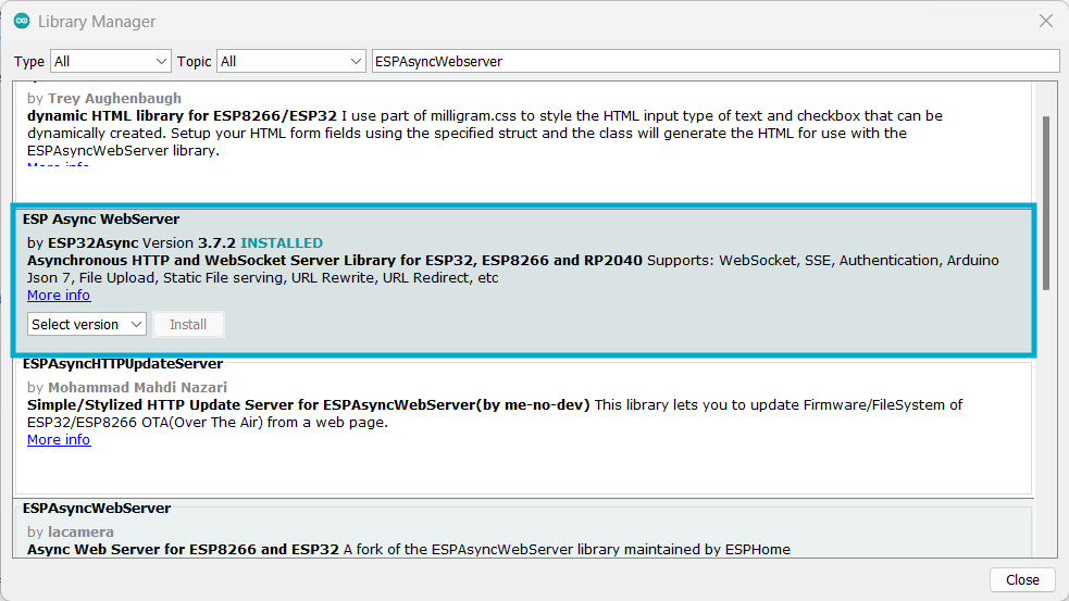
To ensure the code works seamlessly, you’ll need to install the following libraries in your Arduino IDE:
- ESPAsyncWebServer: This library enables the ESP8266 to host an asynchronous web server for serving the water tank monitoring data.
- ESPAsyncTCP: Required for
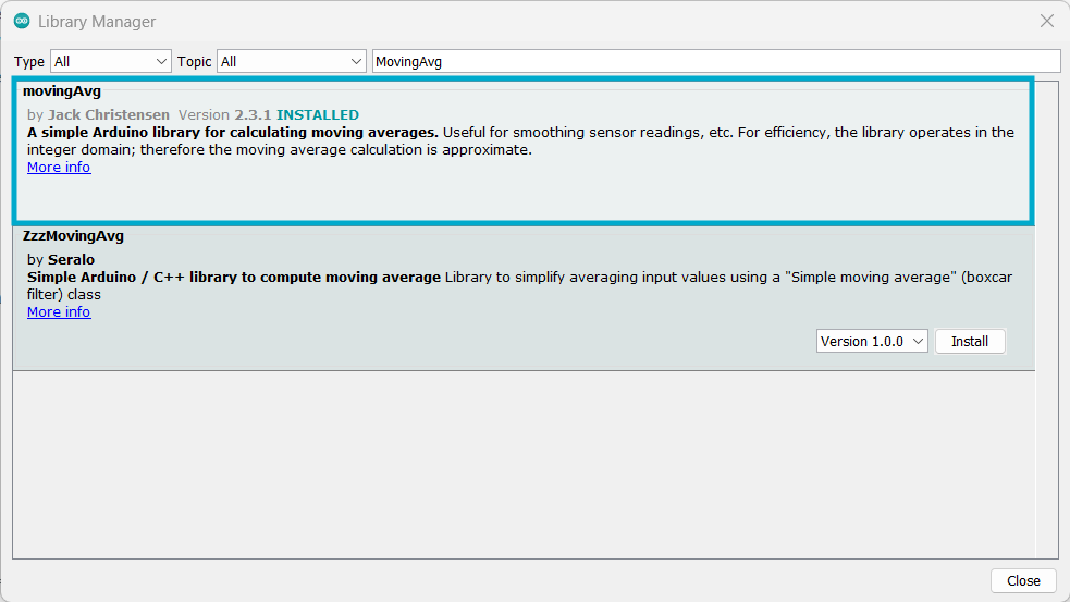
ESPAsyncWebServerto handle asynchronous requests - MovingAvg: This library helps smooth out sensor readings by applying a moving average algorithm.
Steps to Install Libraries:
- Open the Arduino IDE.
- Go to Sketch > Include Library > Manage Libraries in the Arduino IDE.
- Search for ESPAsyncWebServer and install it.
- Search for AsyncTCP and install it.

- Search for MovingAvg and install it.
Alternatively, download them as ZIP files from their GitHub repositories:
Once downloaded, add them using Sketch > Include Library > Add .ZIP Library.
Adding the SPIFFS Filesystem Uploader:
To host the web interface files, we use the SPIFFS filesystem. Here’s how to set it up:
- Download the Project Files:
- Get the provided ZIP file containing the Arduino code and the
datafolder. 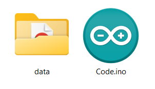
- Get the provided ZIP file containing the Arduino code and the
- Unzip the Files:
- Extract the ZIP file into a folder.
- You’ll see the Arduino sketch and a
datafolder with the web interface files (index.html,style.css,script.js).
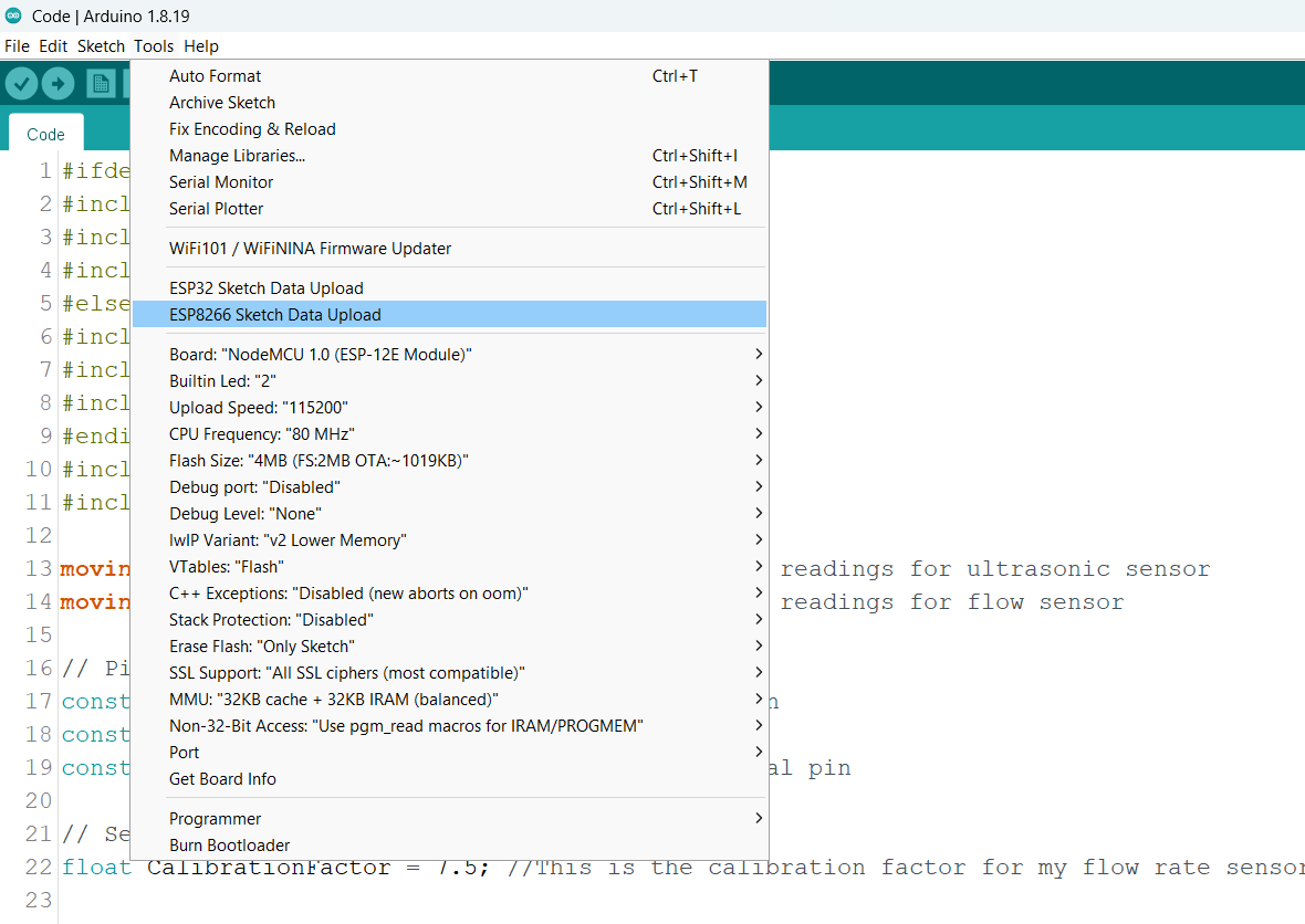
- Upload Files to SPIFFS:
- Open the Arduino sketch in the folder using Arduino IDE.
- Ensure the
datafolder is in the same directory as the sketch. - Go to Tools > ESP8266 Sketch Data Upload and upload the files to the ESP8266.
Note:
If you haven’t installed the SPIFFS uploader tool yet, check out this guide for installation steps: SPIFFS Filesystem Uploader in Arduino IDE.
Web Interface Design
The web interface consists of three files:
- index.html:
- Displays the water level and flow rate visually.
- style.css:
- Provides a clean and modern design for the interface.
- script.js:
- Handles fetching and updating data from the ESP8266 server.
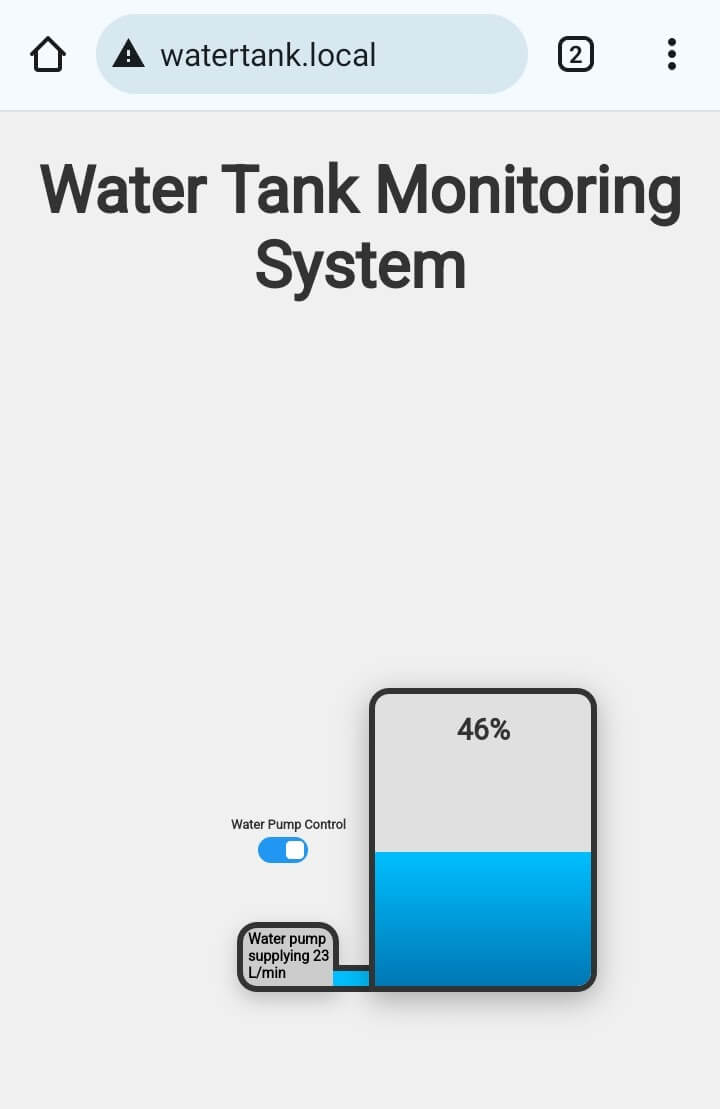
The interface updates every second to provide real-time monitoring. It features:
- A graphical representation of the water level in the tank, showing the current fill percentage.
- A flow rate display showing how much water the pump is supplying in liters per minute.
- A Water Pump Control toggle switch, allowing users to manually turn the pump ON or OFF directly from the web interface.
- A Pump Status Box that dynamically displays the current state of the pump (ON or OFF) and the real-time flow rate when the pump is running.
How It Works
- Ultrasonic Sensor:
- The sensor emits ultrasonic pulses and measures the time it takes for the echo to return.
- The distance is calculated and converted into a percentage based on predefined tank dimensions.
- Flow Sensor:
- The sensor generates pulses proportional to the water flow rate.
- The ESP8266 calculates the flow rate using a calibration factor.
- Pump Control:
- Web interface switch turns pump ON/OFF.
- ESP8266 controls relay based on user input.
- ESP8266 Web Server:
- Hosts the web interface.
- Sends real-time water level and flow rate data to the interface.
- Solar Power System:
- Powers the entire setup using the Solar Power Manager, solar panel, and Lithium-ion battery.
Demonstration
To view the real-time water tank data, follow these steps after setting up the hardware and uploading the code:
- Upload the Arduino Code:
- Ensure the correct board (e.g., FireBeetle ESP8266, NodeMCU, or D1 Mini) and port are selected in the Arduino IDE.
- Compile and upload the Arduino sketch to the ESP8266.
- Connect to Wi-Fi:
- Once powered, the ESP8266 will connect to the Wi-Fi network configured in the code.
- Access the Web Interface:
- Open a web browser on your phone or computer connected to the same network.
- Enter the hostname you set in the code, e.g.,
watertank.local, or the IP address assigned to the ESP8266 by you. - The interface displays real-time data about the water tank, including the current water level, flow rate, and a manual switch to control the water pump directly from the webpage.
On Mobile Phone:
When the Pump is ON
When the Pump is OFF

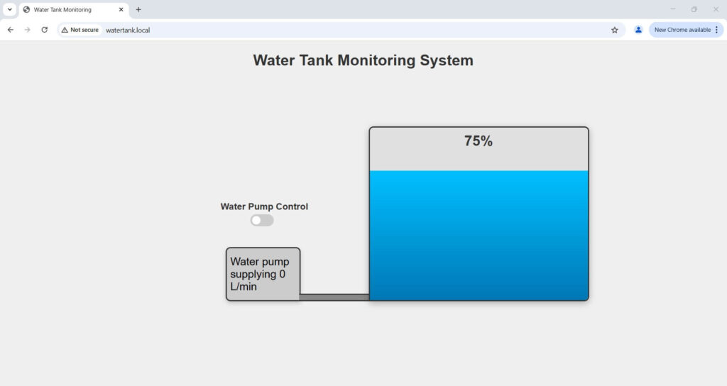
On Desktop:
When the Pump is ON

When the Pump is OFF
Challenges and Solutions
- Wi-Fi Connectivity:
- ESP8266 may struggle to connect if power is unstable.
- Ensure proper power supply and use WiFi.reconnect() for automatic recovery.
- Power Management:
- Solar panel and battery must supply enough power for ESP8266, sensors, and relay.
- Sensor Accuracy:
- Calibrate the flow sensor to improve precision.
- Average ultrasonic sensor readings to reduce noise and fluctuations.
- Manual Control Delay:
- Web switch control may have slight delay due to network or server refresh rate.
Conclusion
This IoT-Based Water Tank Monitoring System using ESP8266 and solar power offers an efficient and reliable solution for real-time monitoring of water levels, flow rates, and pump control. The design ensures accuracy, energy efficiency, and remote access, making it suitable for various scenarios.
Applications:
- Residential water tank monitoring.
- Agricultural irrigation systems.
- Remote water supply management.
You can customize the system further to match your specific needs.
If you have any questions or suggestions, feel free to share them in the comments.
Detailed YouTube Video for Part 1
Here is the detailed YouTube video for this project’s first part: