In this tutorial, we’ll learn how to use a Relay Module with Arduino to control high-voltage devices safely and effectively. This guide covers the basics of relay modules, how to use them with Arduino, and important safety tips to keep in mind.
What is a Relay Module?
A relay module is an electrically operated switch that allows low-power circuits like Arduino to control high-power devices. It uses an electromagnetic relay to switch on or off a device.
Key Features of a Relay Module
- Can control AC or DC devices.
- Optocoupler for isolation (on most modules).
- Single-channel, dual-channel, or multi-channel relay modules available.
- Operates at 5V and connects directly to the Arduino.
Relay Module Basics
Relay modules are designed with:
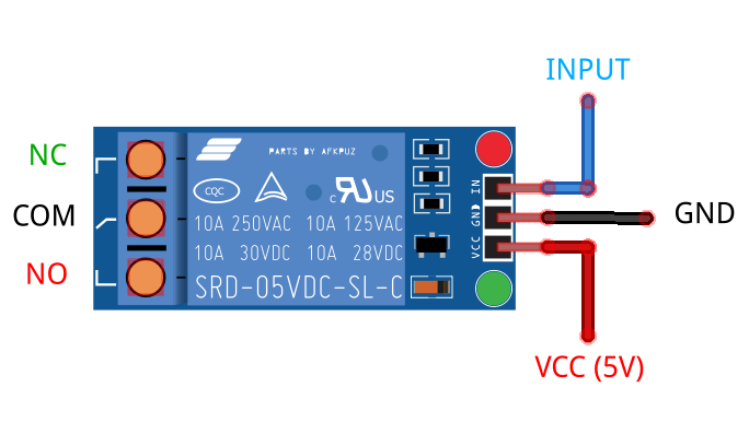
- Input Pins: Typically three pins – VCC, GND, and IN (control signal).
- Output Terminals: COM (Common), NO (Normally Open), and NC (Normally Closed).
- Indicator LED: Shows the relay’s activation state.

How Does a Relay Work?
A relay operates as an electrically controlled switch. It uses a small input current from a low-power device, such as an Arduino, to control the flow of a larger current in a separate circuit.
Inside the relay, an electromagnet is activated when a signal is sent to the input pin. This electromagnetic force moves a mechanical switch, either opening or closing the circuit connected to the relay’s output terminals. This mechanism allows a low-voltage control signal to safely and effectively switch high-voltage or high-current devices, such as motors, lights, or appliances.

Key Points:
- The control side (input) and load side (output) of the relay are electrically isolated, ensuring safety.
- The relay has two states:
- Normally Open (NO): Circuit is open (off) until the relay is activated.
- Normally Closed (NC): Circuit is closed (on) until the relay is activated.
This design makes relays an essential component for interfacing low-power control systems with high-power devices.
Required Components
To follow this tutorial, you’ll need:
- Arduino Uno
- 5V relay module
- Jumper wires
- Breadboard
- A 220V light bulb or small DC motor (for demonstration)
- Power supply for the load (e.g., 220V AC for appliances or 12V DC for motors)
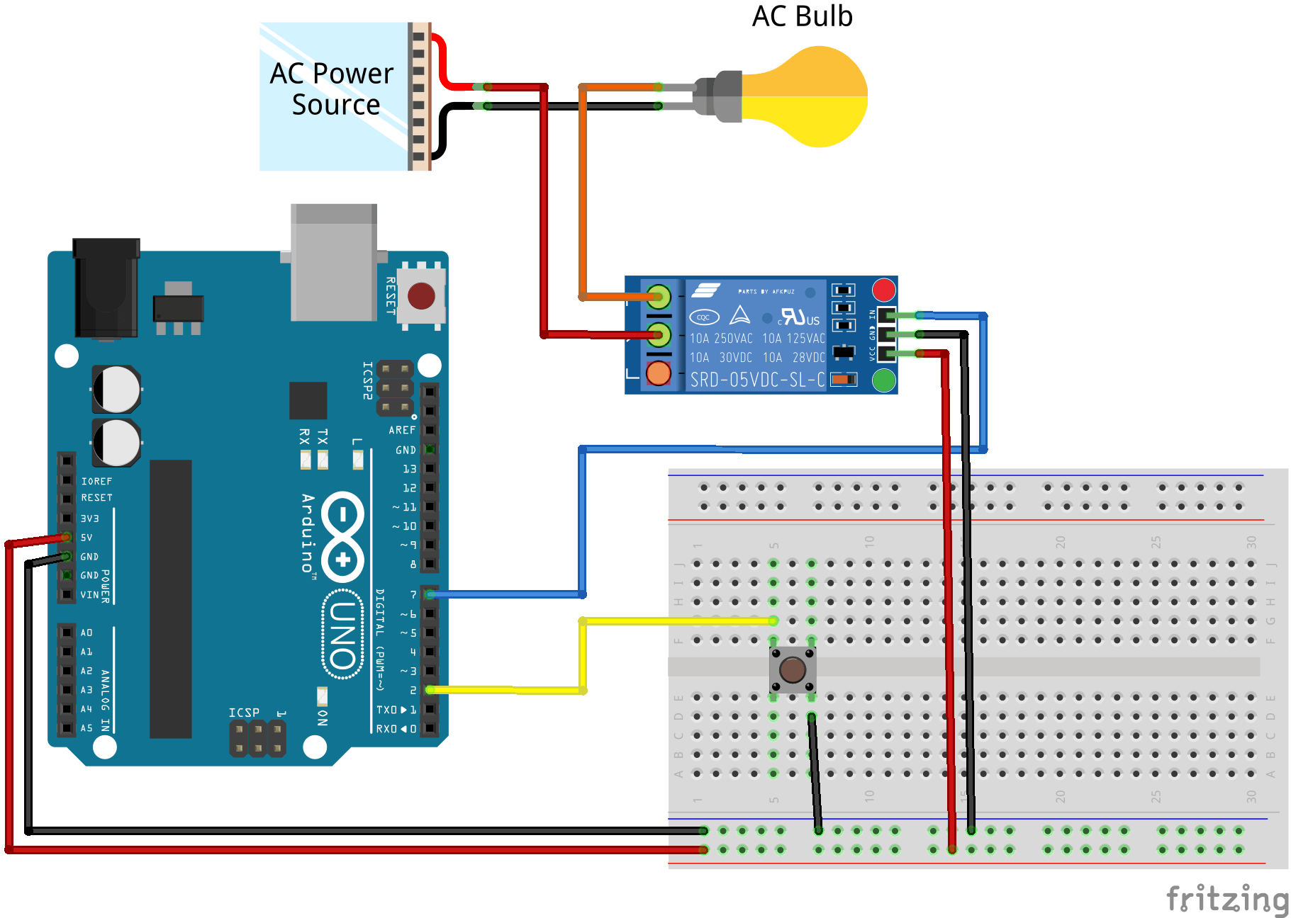
Circuit Diagram
Connections:
- Relay Module Pins:
- VCC → 5V on Arduino
- GND → GND on Arduino
- IN → Digital Pin 7 on Arduino
- Load Connections:
- Common (COM) → Load power source (e.g., 220V AC or 12V DC).
- Normally Open (NO) → One end of the load.
- The other end of the load connects to the power source ground or neutral.

Code for Relay Module with Arduino
Here’s the Arduino sketch to control a relay module. In this example, the relay is triggered when a button is pressed.
// Relay Module with Arduino by ArduinoYard
#define RELAY_PIN 7  // Relay module connected to digital pin 7
#define BUTTON_PIN 2 // Button connected to digital pin 2

void setup() {
  pinMode(RELAY_PIN, OUTPUT); // Set relay pin as output
  pinMode(BUTTON_PIN, INPUT_PULLUP); // Set button pin as input
  digitalWrite(RELAY_PIN, LOW); // Initialize relay in OFF state
  Serial.begin(9600);
}

void loop() {
  if (digitalRead(BUTTON_PIN) == LOW) { // Button pressed
    digitalWrite(RELAY_PIN, HIGH); // Turn relay ON
    Serial.println("Relay is ON");
  } else {
    digitalWrite(RELAY_PIN, LOW); // Turn relay OFF
    Serial.println("Relay is OFF");
  }
}
Explanation of the Code
- Defining Pins:
RELAY_PINandBUTTON_PINdefine the relay and button pins. - Initialization: The relay pin is set as output and button pin as input with a pull-up resistor.
- Control Logic: When the button is pressed, the relay is activated, turning on the connected device.
Testing the Circuit
- Upload the code to your Arduino Uno.
- Press the button to activate the relay.
- When activated, you’ll hear a clicking sound from the relay.
- The connected load (light bulb, motor, etc.) will turn on or off accordingly.
To visualize and simulate this circuit without physical components, we’ll use the Wokwi Arduino Simulator. Wokwi allows you to create, test, and simulate Arduino circuits online. It’s a great tool to validate your code and understand circuit behavior before building it in real life.
You can find a pre-built Wokwi simulation for this relay circuit here. Simply click the link, load the simulation, and observe the relay activation as the button is pressed.
Multi-Channel Relay Modules
Relay modules come in various configurations, such as 1-channel, 2-channel, 4-channel, 8-channel, or more. These modules allow you to control multiple devices simultaneously with a single Arduino board. For example:
- A 2-channel relay module can control two appliances independently.
- An 8-channel relay module is useful for more complex projects, such as home automation systems.
Each relay in a multi-channel module works independently, so you can control them individually using separate Arduino pins. The wiring and code are similar to a single-channel relay, but you need to specify the appropriate control pin for each relay.
Active LOW vs. Active HIGH Relays
Relay modules can be configured as Active LOW or Active HIGH, depending on their design.
- Active LOW: The relay is activated when the control signal is LOW (0V).
- Active HIGH: The relay is activated when the control signal is HIGH (5V).
To determine the type of your relay module:
- Check the Manufacturer’s Datasheet: Look for the module specifications.
- Experiment with a Test Circuit: Use an Arduino or a simple 5V input signal. If the relay clicks ON when the control pin is grounded, it’s Active LOW. If it clicks ON when the pin receives 5V, it’s Active HIGH.
Pro Tip: Some relay modules have a jumper or solder pads to switch between Active LOW and Active HIGH modes.
Understanding Relay Module Ratings and Voltage Requirements
When using a relay module with Arduino, it’s crucial to choose the correct voltage relay. A 5V relay module is suitable for Arduino since it matches the control signal from the Arduino pins. A 12V relay module, however, will not work directly because the Arduino’s 5V control signal cannot activate it.
How to Identify the Voltage Rating
You can determine the relay’s voltage rating by checking the markings on its casing. For example:
- SRD-05VDC-SL-C: This indicates a 5V relay.
- SRD-12VDC-SL-C: This indicates a 12V relay.
Key Ratings on the Relay Casing
Relay modules display additional specifications on their casing. Here’s what they mean:
- Voltage (e.g., 5V DC): Operating voltage of the relay coil.
- Current (e.g., 10A): Maximum current the relay contacts can handle.
- Voltage Rating (e.g., 250V AC, 30V DC): Maximum voltage the relay can safely switch.

Always ensure that the load you connect (e.g., light bulb, motor) does not exceed the relay’s ratings.
Safety Precautions
- When working with high-voltage devices, always follow proper safety guidelines to avoid accidents or equipment damage.
- Always handle high-voltage connections with care.
- Use proper insulation to avoid electric shocks.
- Avoid directly handling the circuit while it’s powered.
Applications of Relay Module with Arduino
- Home Automation: Control lights, fans, and other appliances remotely.
- Industrial Automation: Operate heavy machinery with microcontrollers.
- IoT Projects: Pair with Wi-Fi modules like ESP32 for remote control.
- Security Systems: Use with sensors to automate alarms or locks.
Conclusion
This guide has covered everything you need to know about using a Relay Module with Arduino, from basics to advanced tips like handling multi-channel modules and distinguishing between Active LOW and Active HIGH relays.
With this knowledge, you can confidently use relay modules to control high-voltage devices in your Arduino projects.
Recommended Links:
- Use Relay in a Useful Scenario: Automatic Room Light Control
- Learn about PWM Control: ESP32 Webserver PWM Control
- Explore Sensor Tutorials: DHT11 and DHT22 Sensors with Arduino
- Get Started with Displays: Using IR Sensor with Arduino
